Measure twice, etch four times
A real CDJ taken apart and measured photo by photo, a chassis drawn around it, a 3D printer, boards etched at home with a laser, and the first controller board of its own.

A deck is played by feel. The jog wheel has to sit where the hand expects it, the tempo fader has to travel the length a DJ’s thumb knows, and the buttons have to be where a CDJ has them. So before drawing a chassis, TriMixxx needed the real thing’s measurements, and the most reliable source was a real deck.
A CDJ on the bench
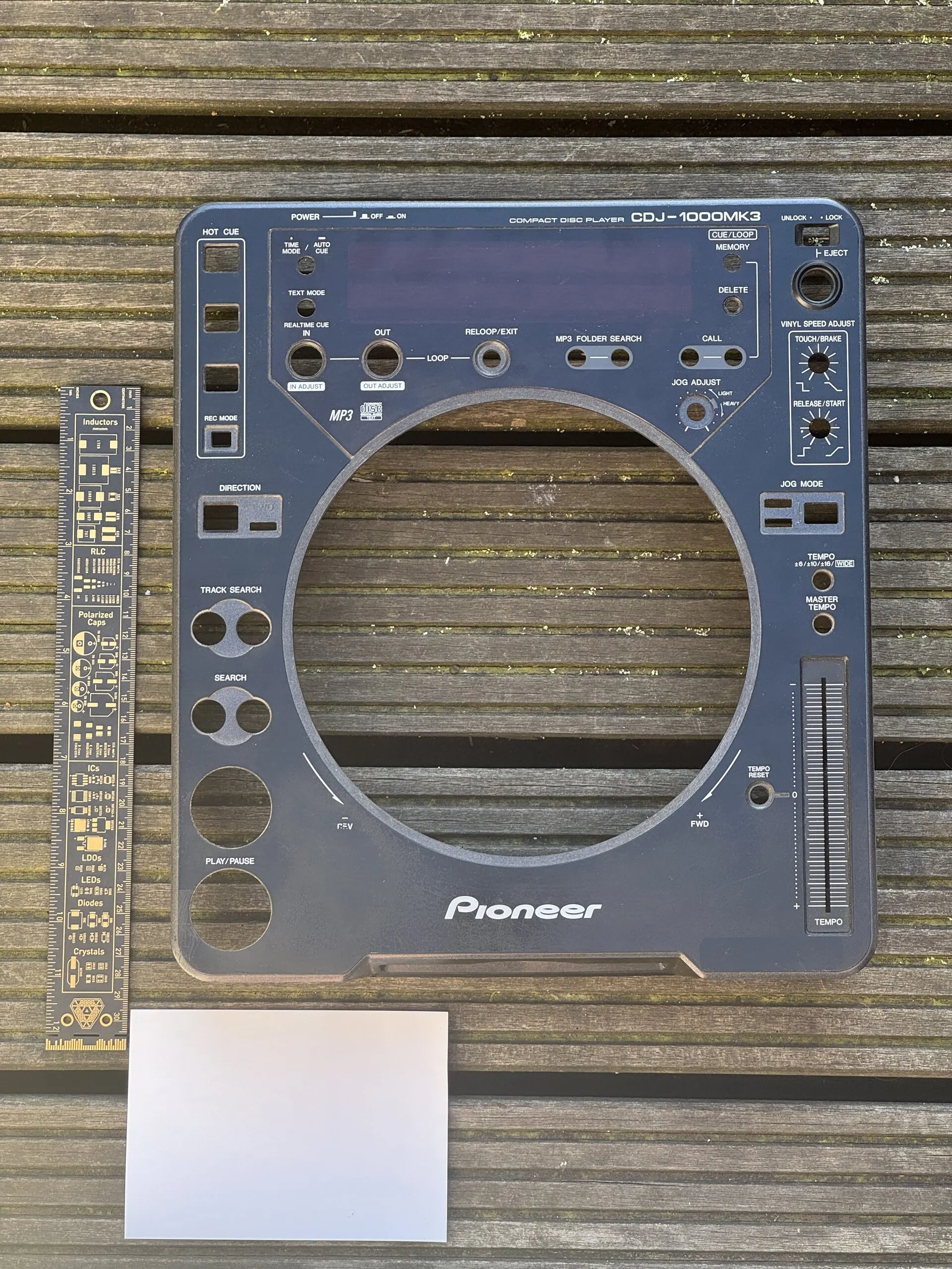
The CDJ-1000MK3 opened in February went back on the bench in April. Its top case, bottom case and jog assembly were photographed flat beside references of known size, then measured on the photos: every hole, every control, the jog’s diameters and its height above the panel.
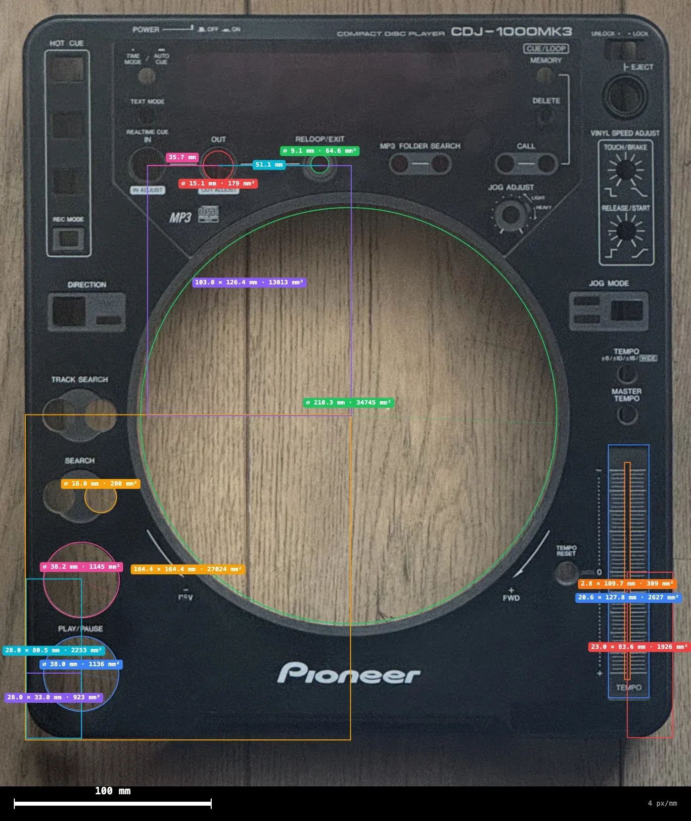
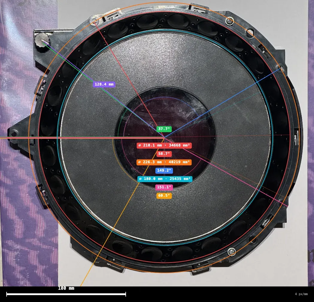
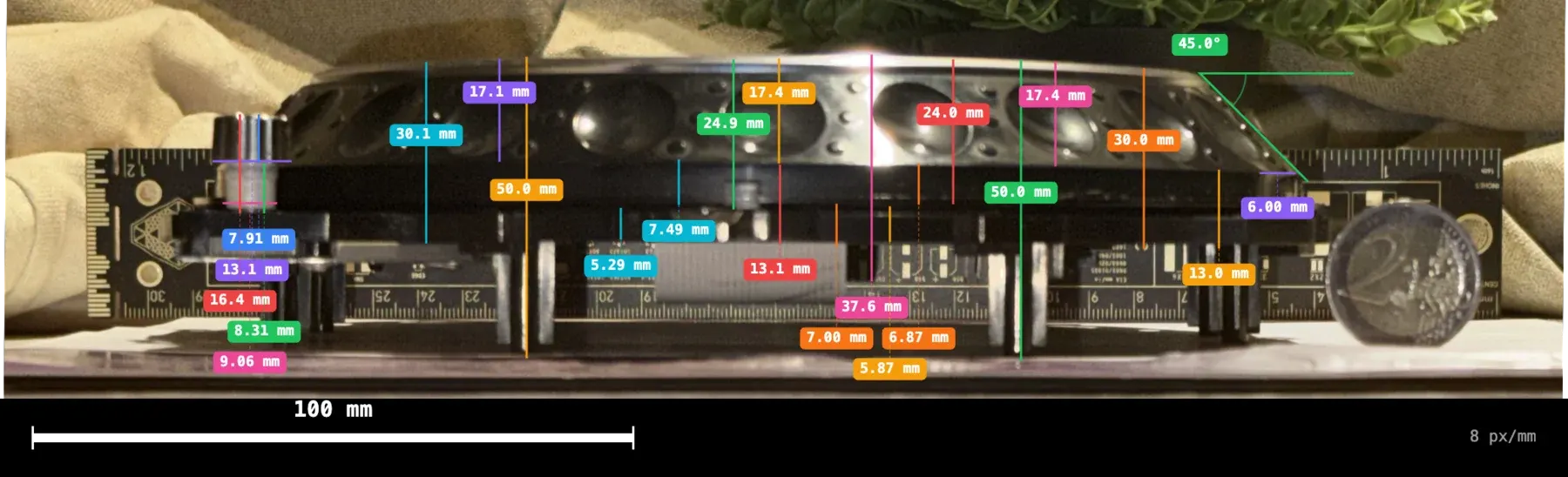
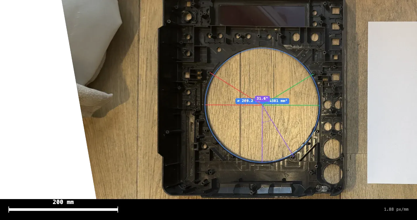
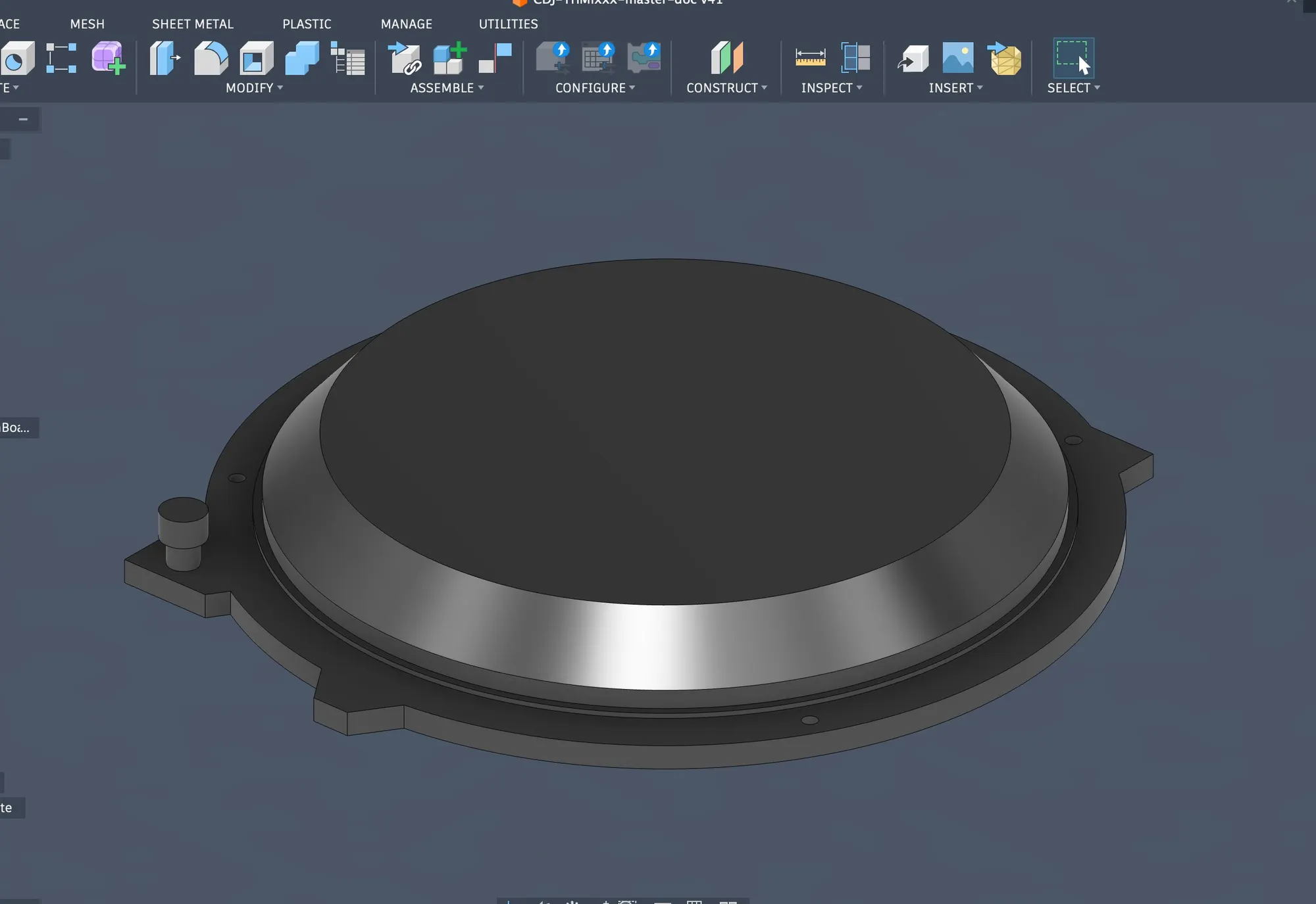
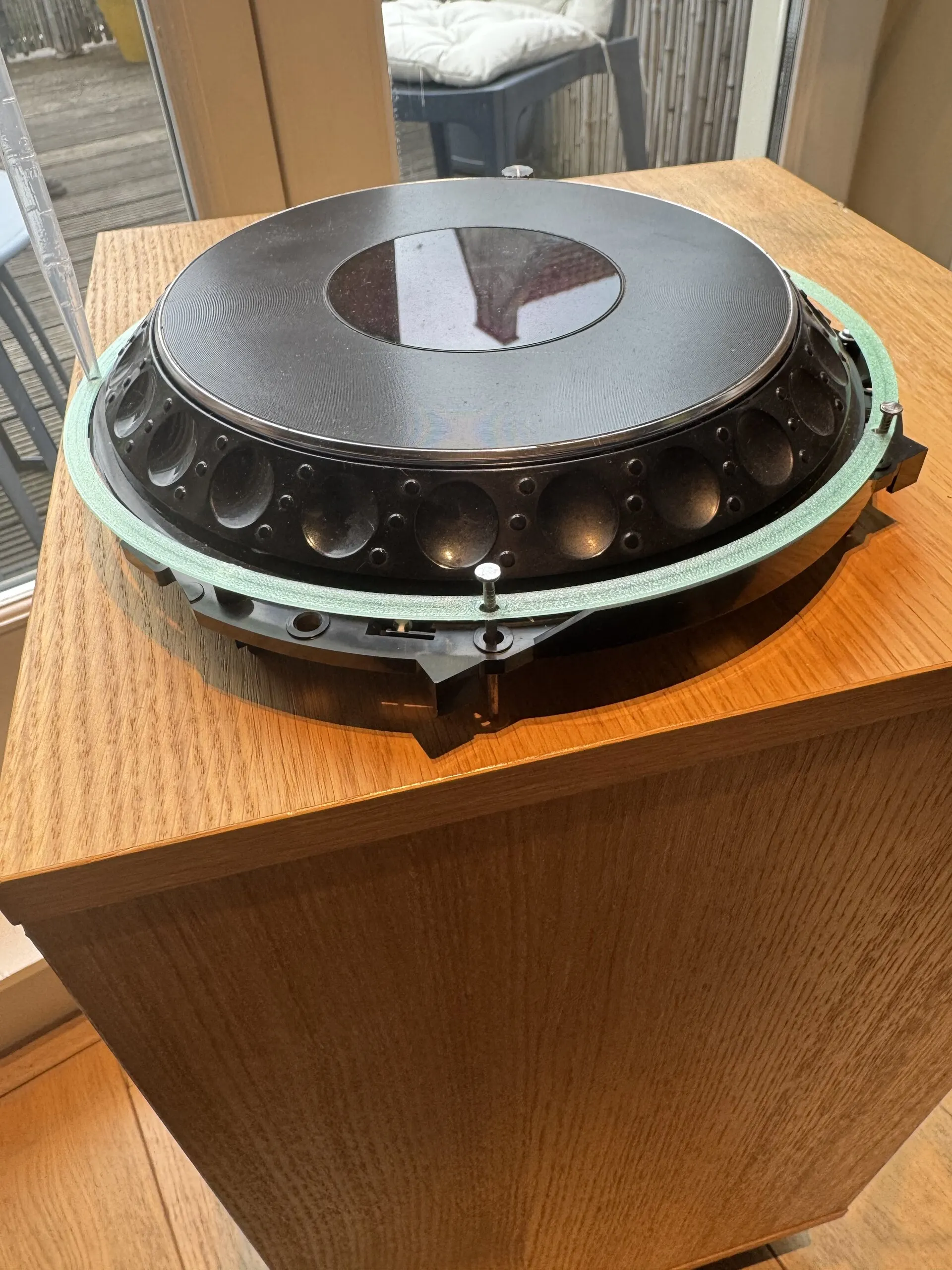
The jog assembly didn’t just give its measurements: it went into the deck. TriMixxx’s jog wheel is a CDJ-1000MK3’s, optical encoder and touch switch included.
The first chassis
The first full chassis, drawn in Fusion 360, borrowed a CDJ-3000’s envelope: 453 × 329 × 118 mm. In mid-May a 3D printer arrived, a Bambu Lab H2D, and the parts started coming out in carbon-fibre PETG.
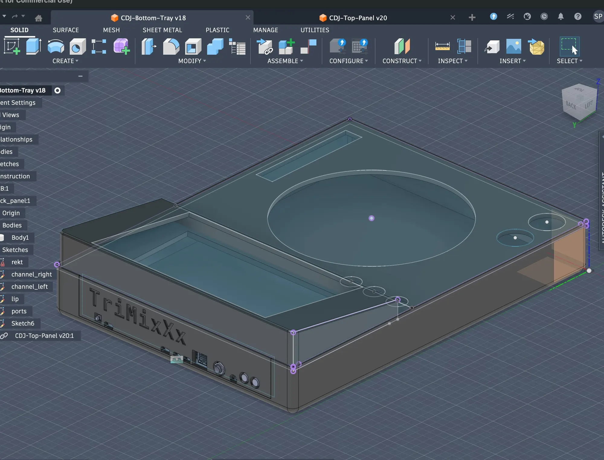
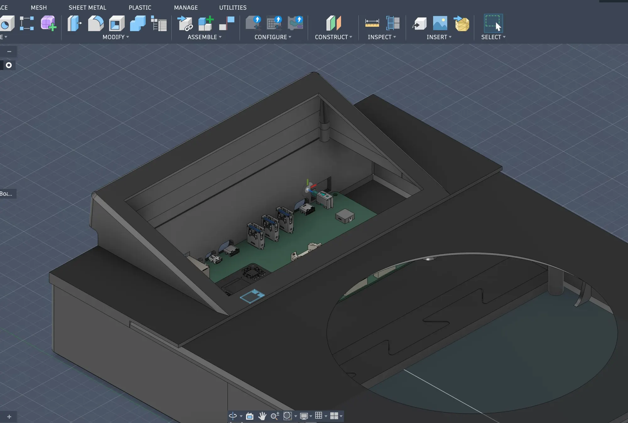
The first models still had the monolithic board in mind: in early May, the long green board was still drawn under the screen.
Printing meant test fits, and test fits meant numbers that were wrong. The circle of screws holding the jog, measured at 226.3 mm, turned out 4.1 mm too large; it became 222.4 mm, keeping a little clearance. The jog-tension dial’s position took several versions, one of which, in the notes’ own words, adjusted 1.7 mm the wrong way. Parts that didn’t quite fit the printer needed an overhang correction factor, logged with a plea to the gods of CAD.
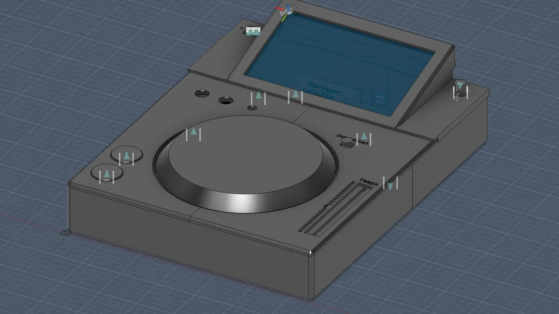
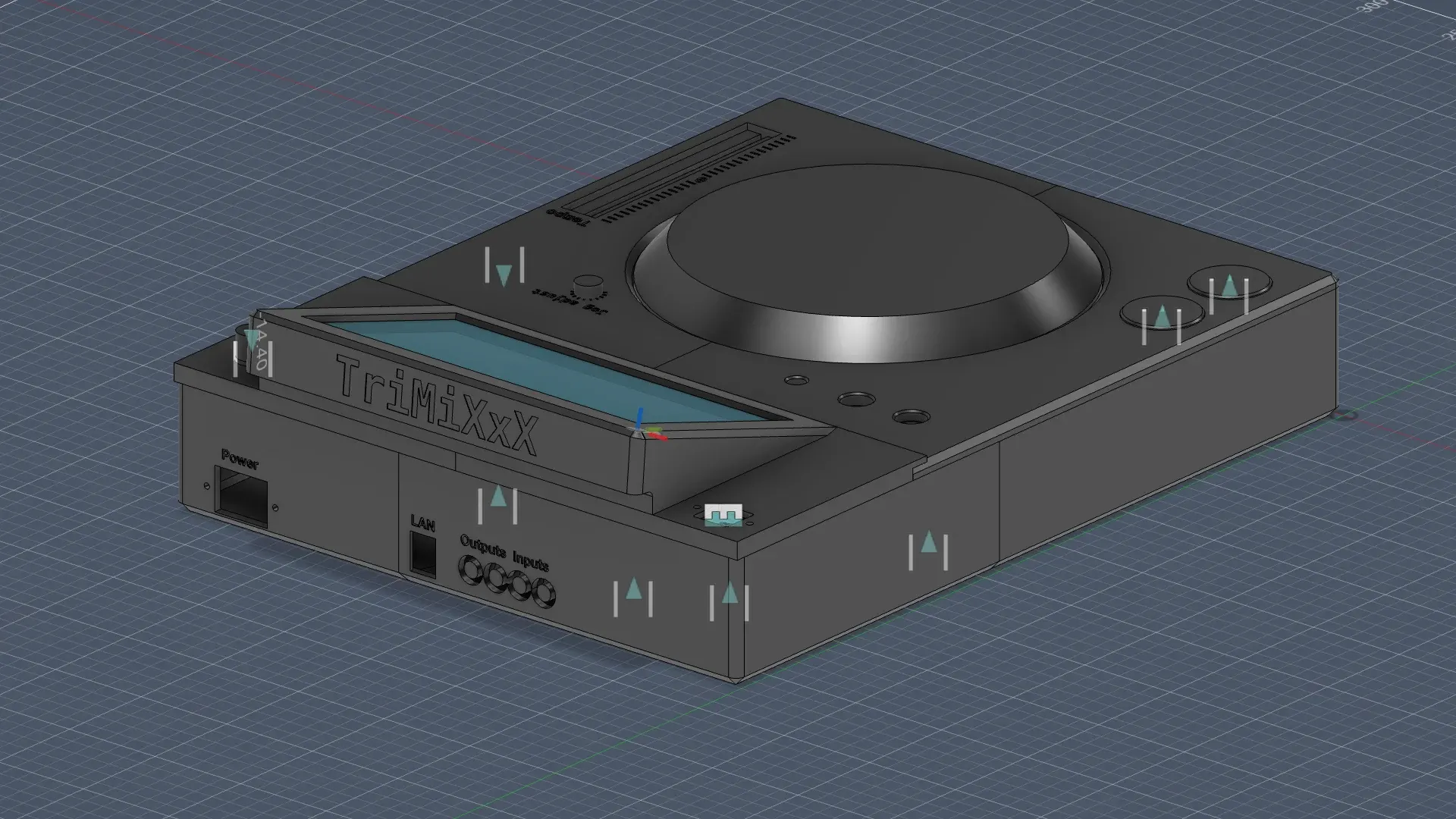
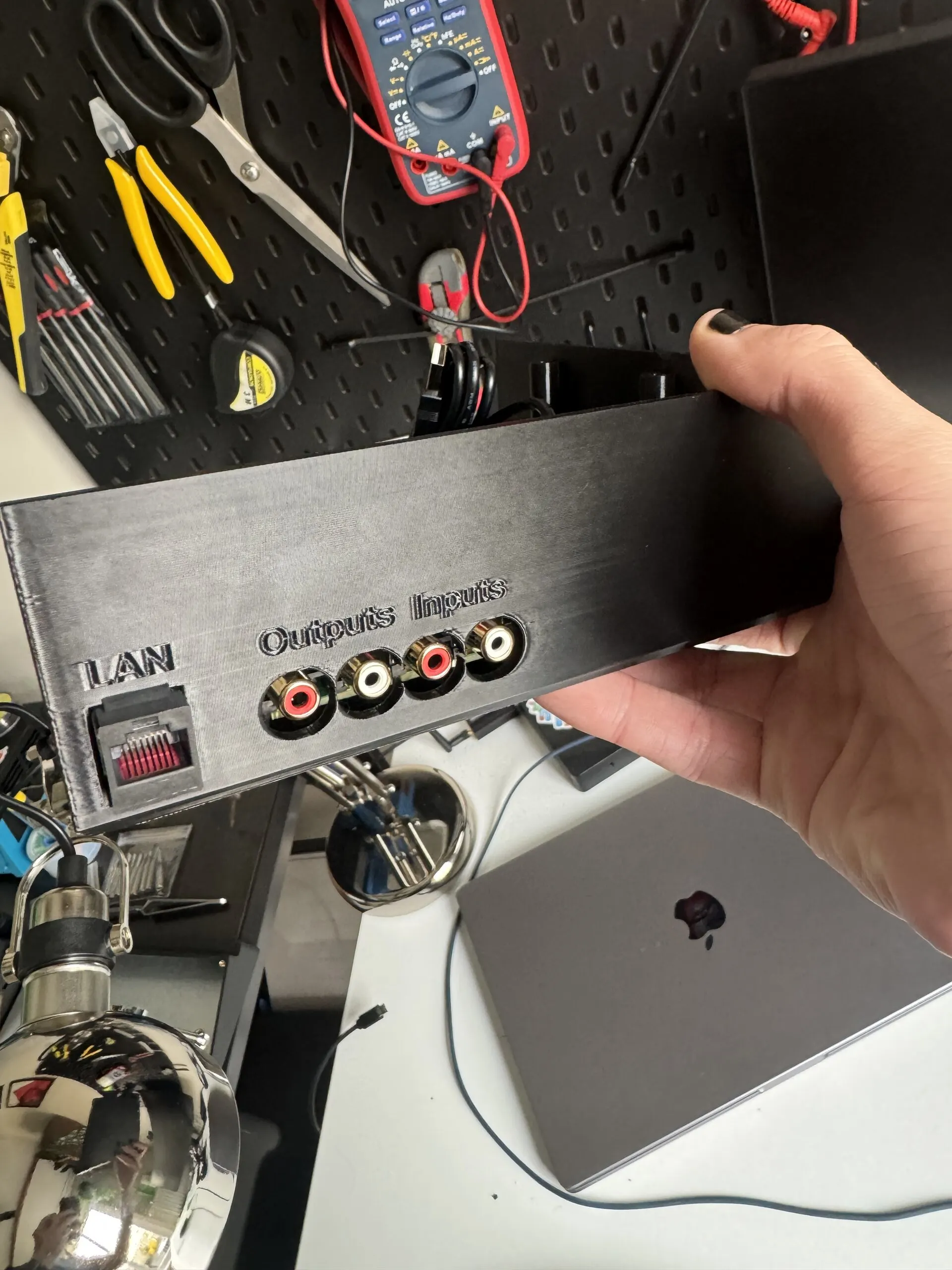
The printer’s bed is smaller than a deck, so the biggest panels were printed in pieces, joined on a zig-zag seam and welded with melted plastic. The first electronics went into the printed tub the day after the printer arrived: a Raspberry Pi 4, an audio board and a mains supply.
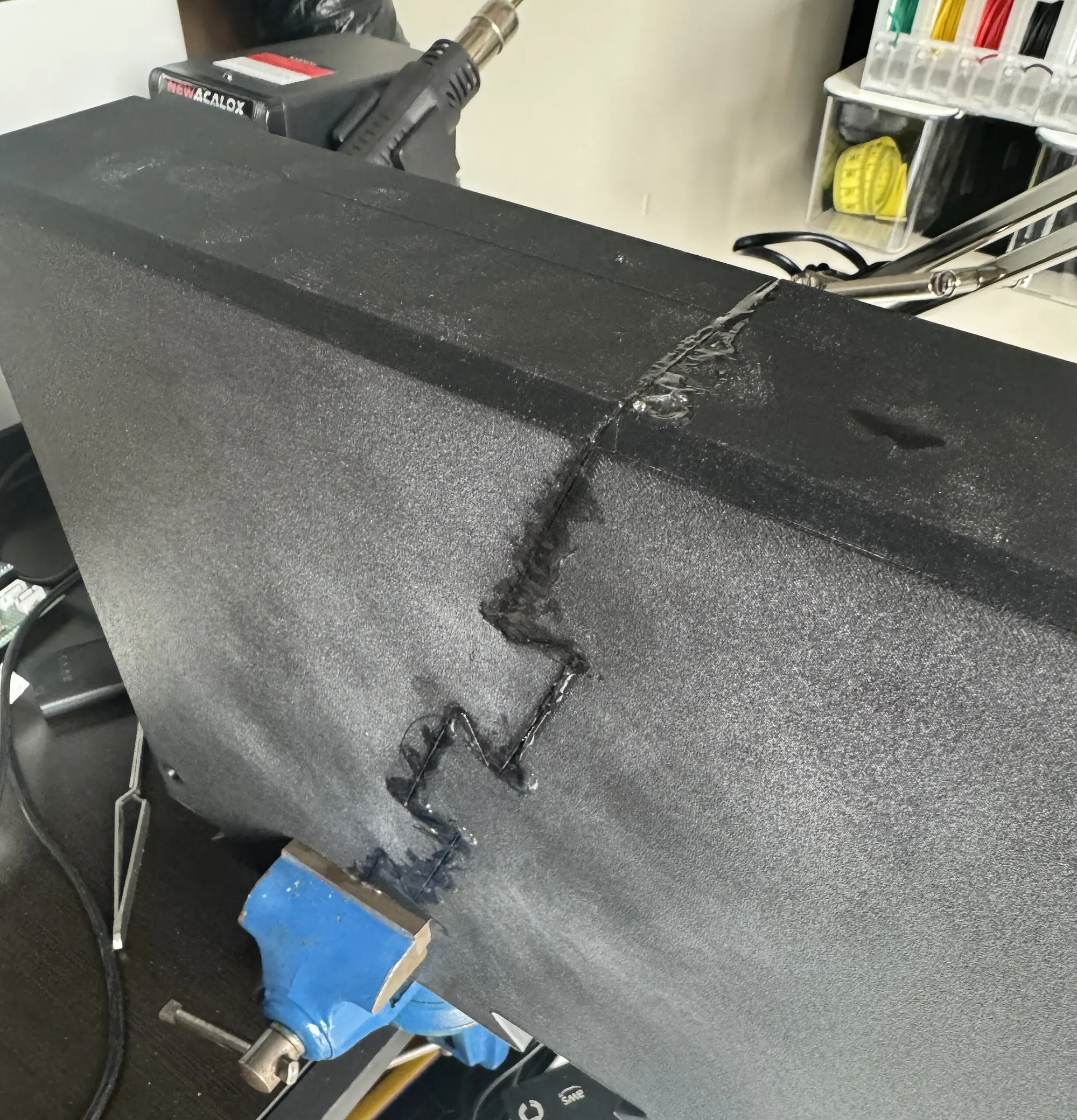
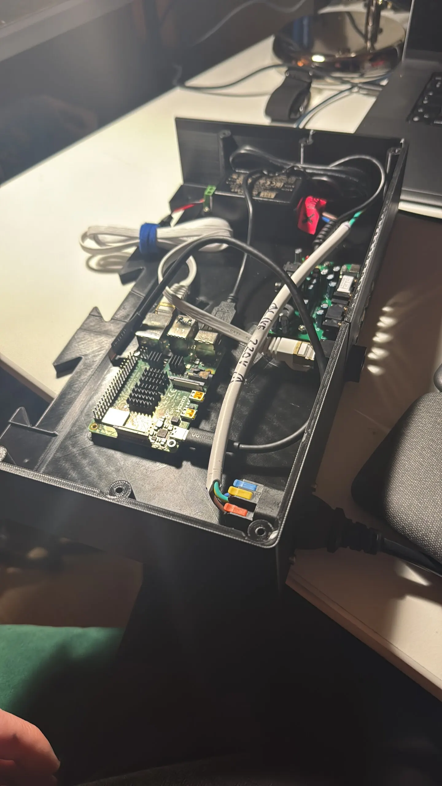
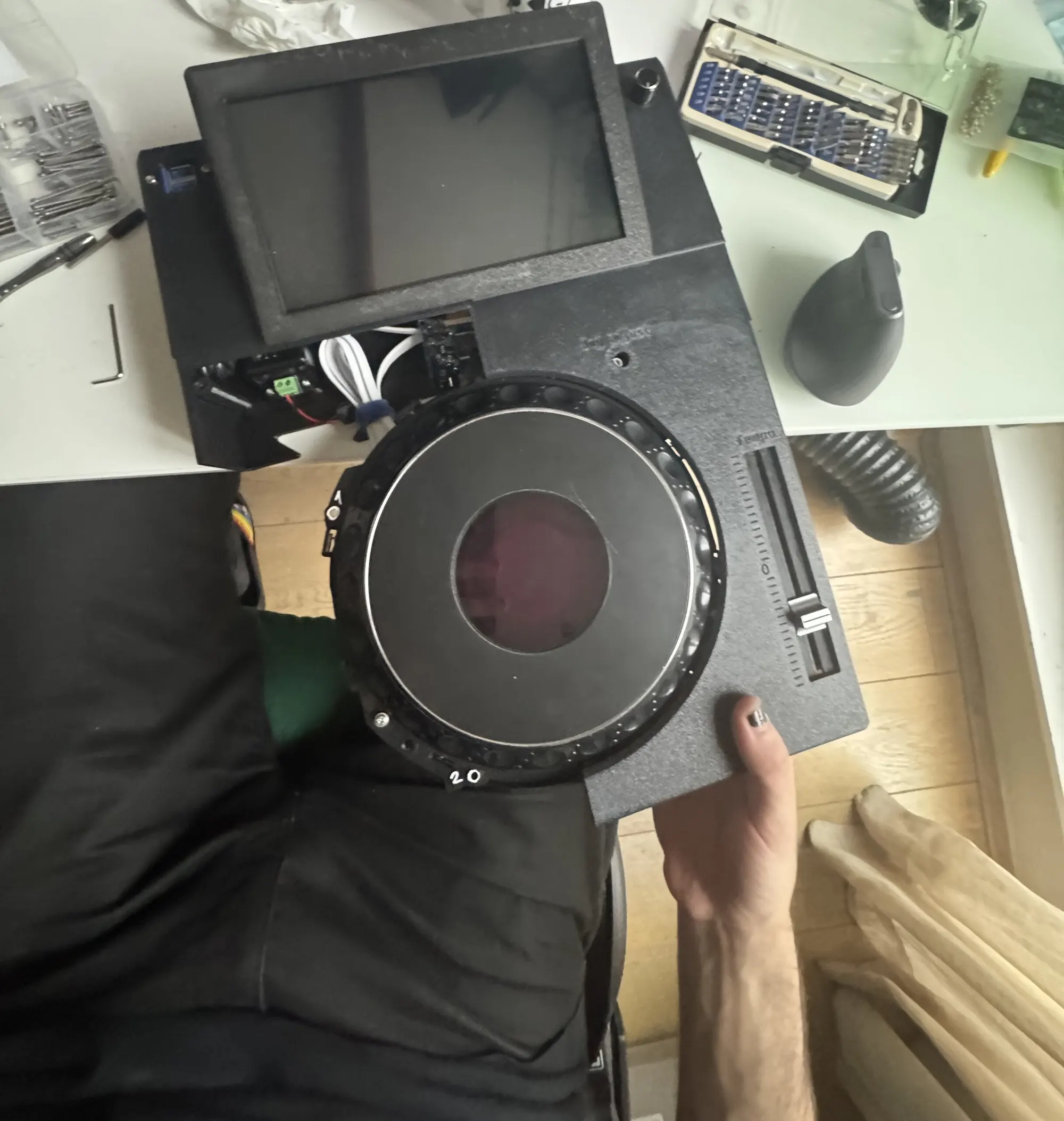
By June 1st the model was at its 117th version, and it already held a decision that would outlive the monolithic board: the sound would come from a Behringer UCA222, an off-the-shelf USB sound card, rather than a DAC of TriMixxx’s own.
Circuit boards in an afternoon
Ordering boards from a factory takes a week or two. For the simple boards, the PLAY/CUE board and the loop board, which are only switches and LEDs, a faster loop was possible: make them in the workshop.
The process: spray-paint copper-clad board, plot each copper layer from KiCad as a negative, let the laser burn the paint off wherever copper has to go, etch the bare copper away in ferric chloride, then drill the holes by hand. A small script, make_bambu_ready.py, turns KiCad’s plots into files the laser understands.
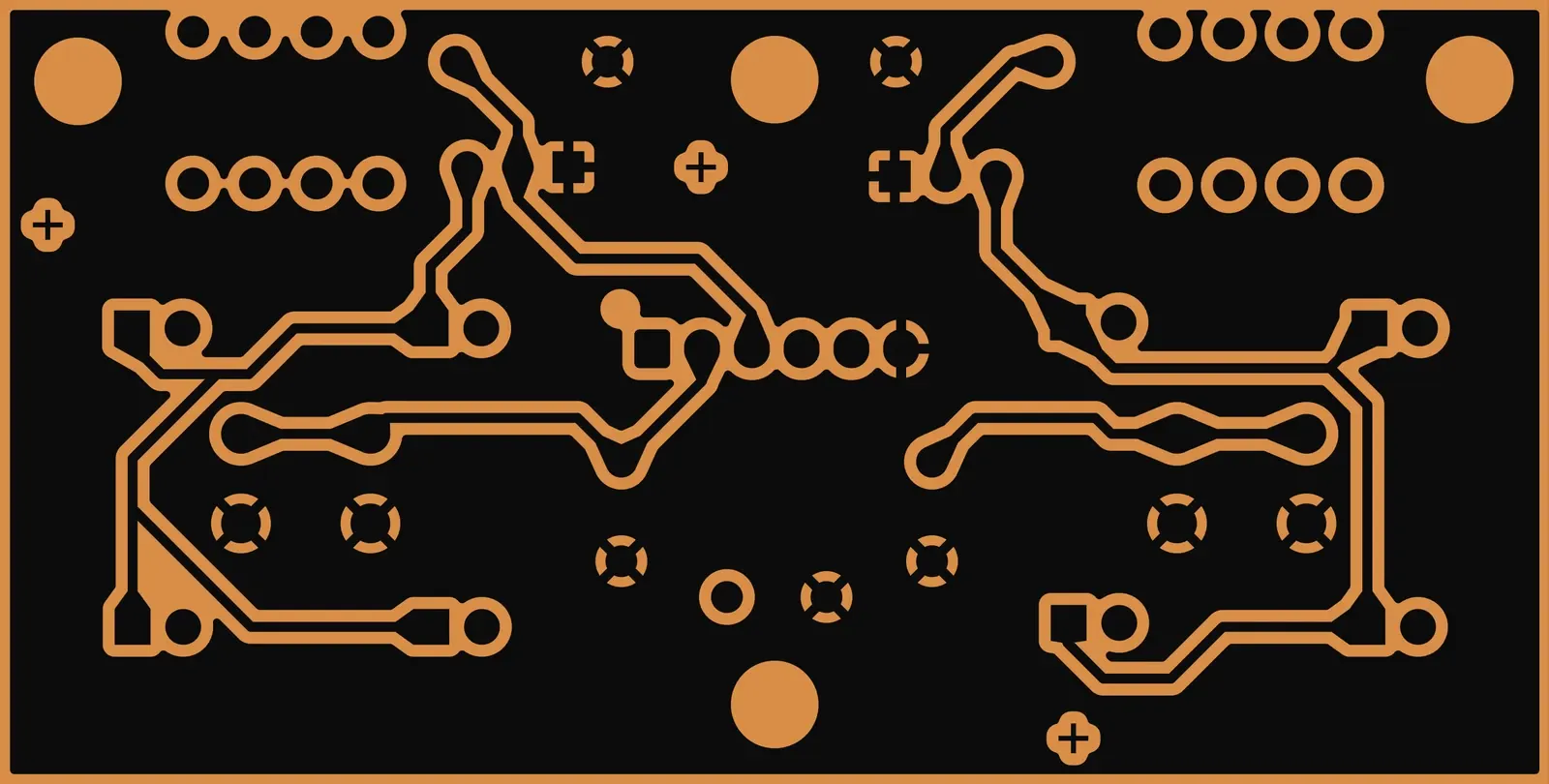
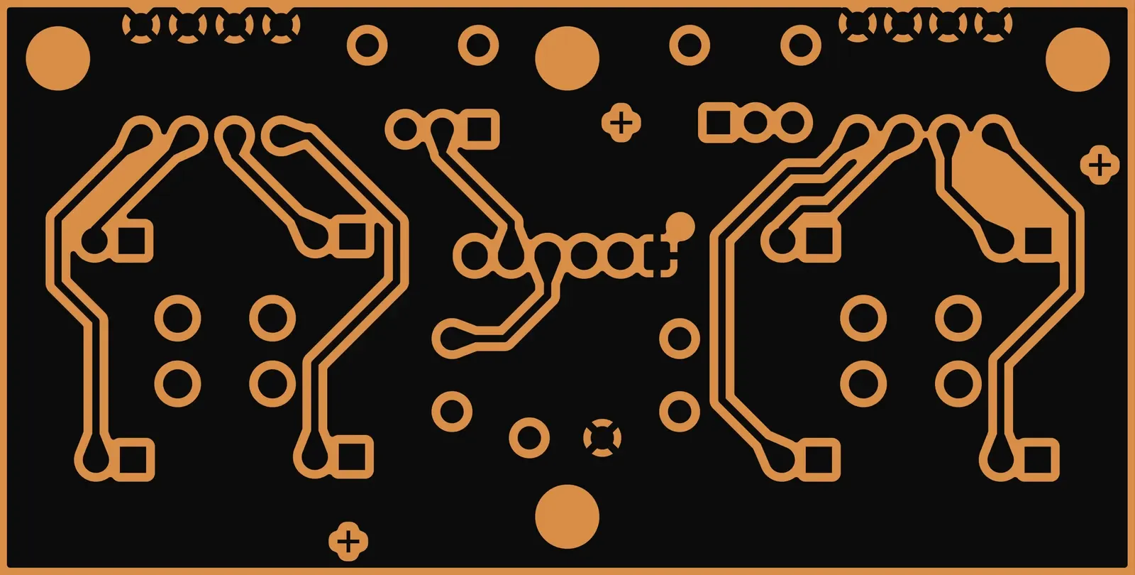
The first attempts didn’t line up. The laser software ignores an SVG’s viewBox, so the two sides of a board were offset from each other, and it took four attempts to find out why. On 9 June the fix went into the script, with a commit message that won’t be quoted here; on 10 June both boards were lasered and etched.
Boards meant for the laser follow their own design rules: tracks and gaps of at least 0.4 mm to absorb the etch’s undercut, 0.4 mm between copper and holes for a hand drill’s drift, and no plated holes at all, since a via here is a wire soldered on both sides. These two boards have none. The same boards were then prepared for JLCPCB too.
The first controller of its own
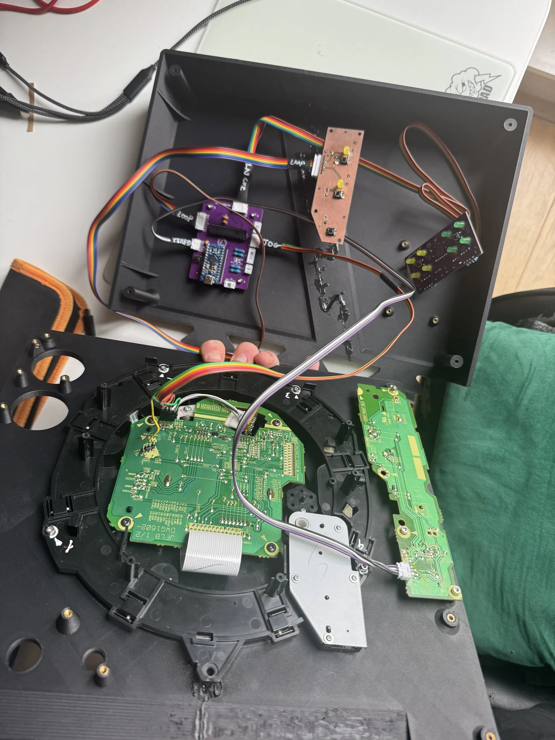
The monolithic board had planned an ATmega32U4 to read the controls. In late May that idea became a perfboard, then a board of its own: midi-laser-pcb, an Arduino Pro Micro and an MCP23017 I²C expander on 80 × 60 mm, with JST connectors for every group of controls.
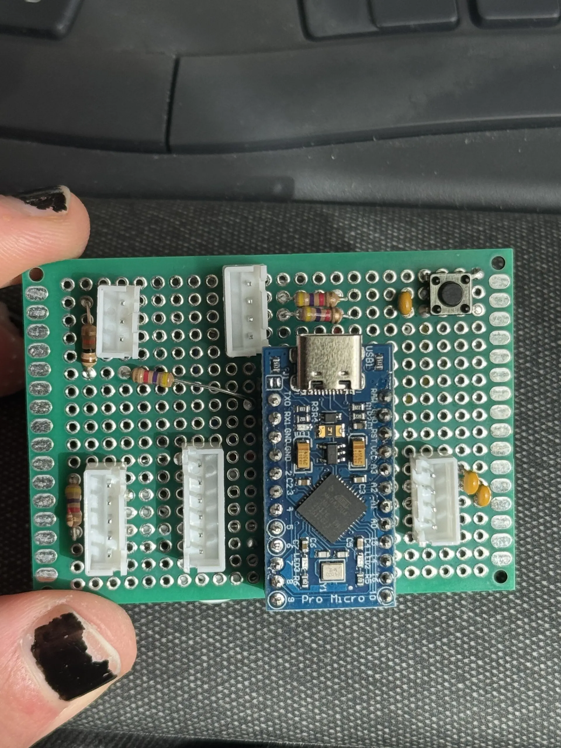

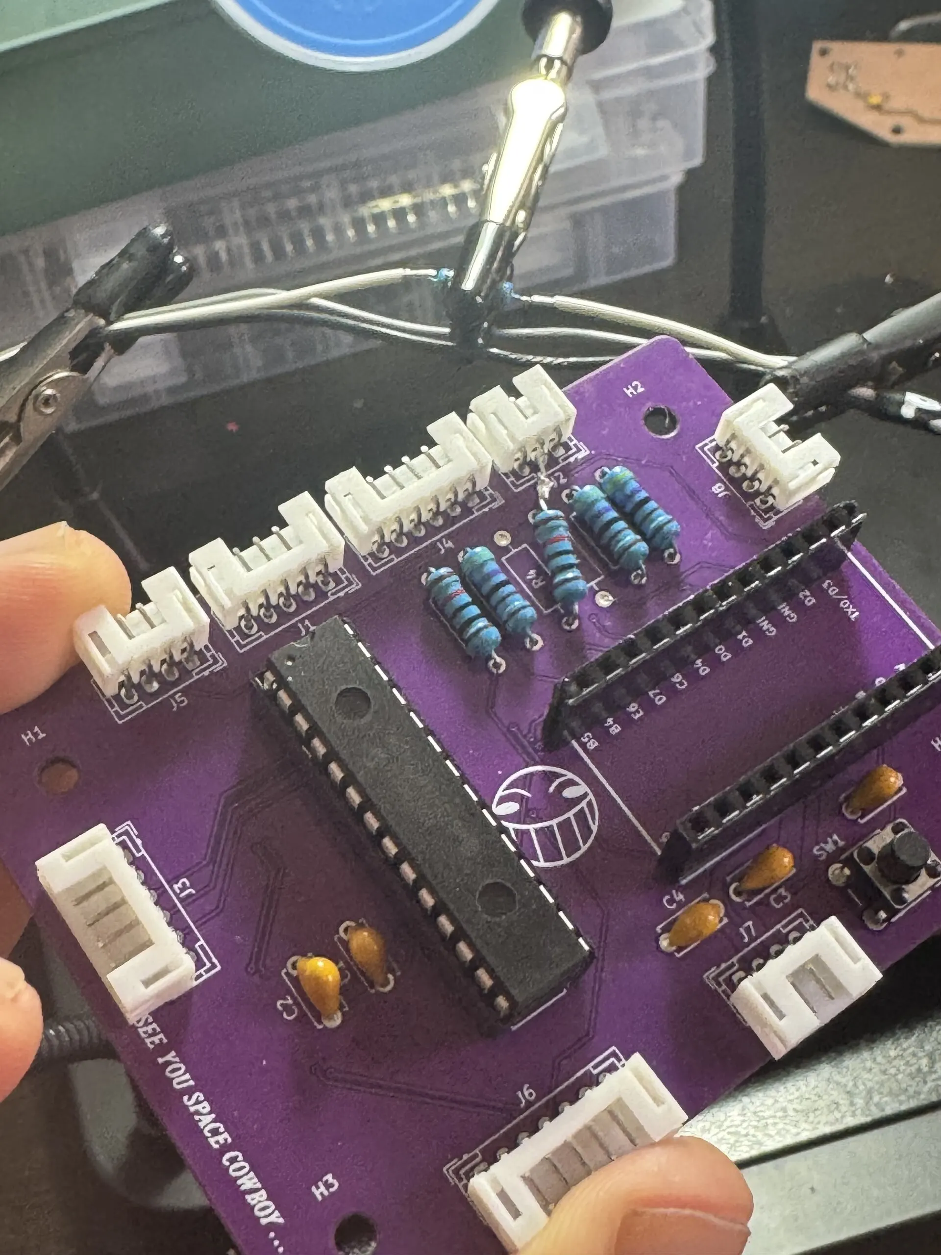
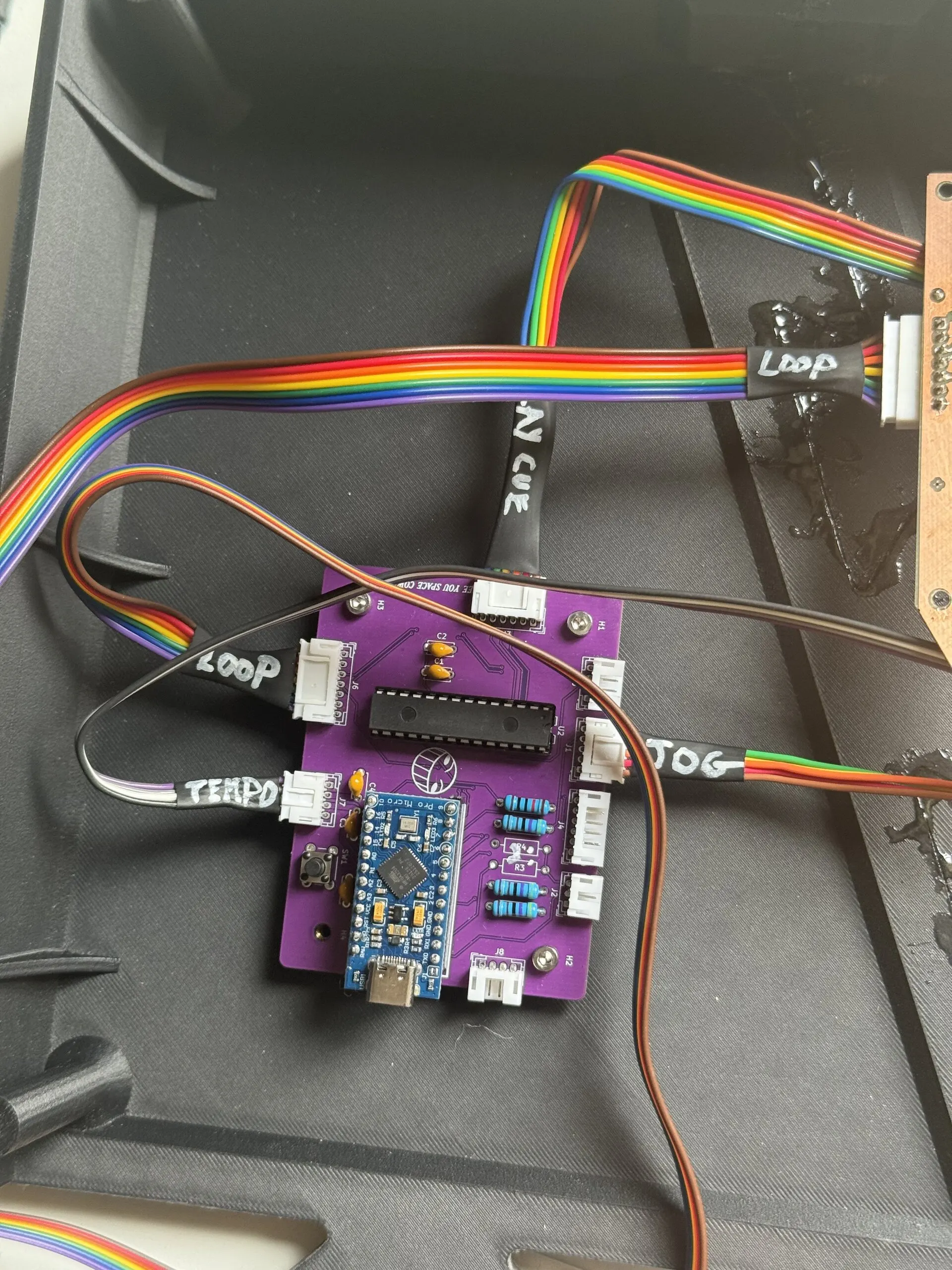
It came back from the fab on 25 June, and was brought up on 30 June with a test sketch, and the bring-up wrote its own to-do list for a second version: no pinouts on the silkscreen; a 5 V to 3.3 V divider on the receive line that belonged on the transmit line; the RELOOP button never wired to the expander; and the jog encoder on pins without interrupts, which “may slip at full scratch”.
That second version was never ordered. The same day, a different board was drawn: one built around an ESP32-S3, with hardware made for counting a jog wheel, two cores, and UARTs to spare. That board, and the rings of tiny pad boards it drives, are the next part of the story.