A deck is a network
Instead of one board that does everything, an ESP32-S3 in the middle and rings of tiny RISC-V boards for the pads, passing a single frame round at 500 kbaud. With white LEDs, a dying pin and a baud rate off by two along the way.

The monolithic board put everything in one place, and paid for it with every mistake. July 2026 tried the opposite: many small boards, each doing one job, talking over the simplest links there are. Where a CDJ has a main board, TriMixxx now has a small network.
The brain: an ESP32-S3
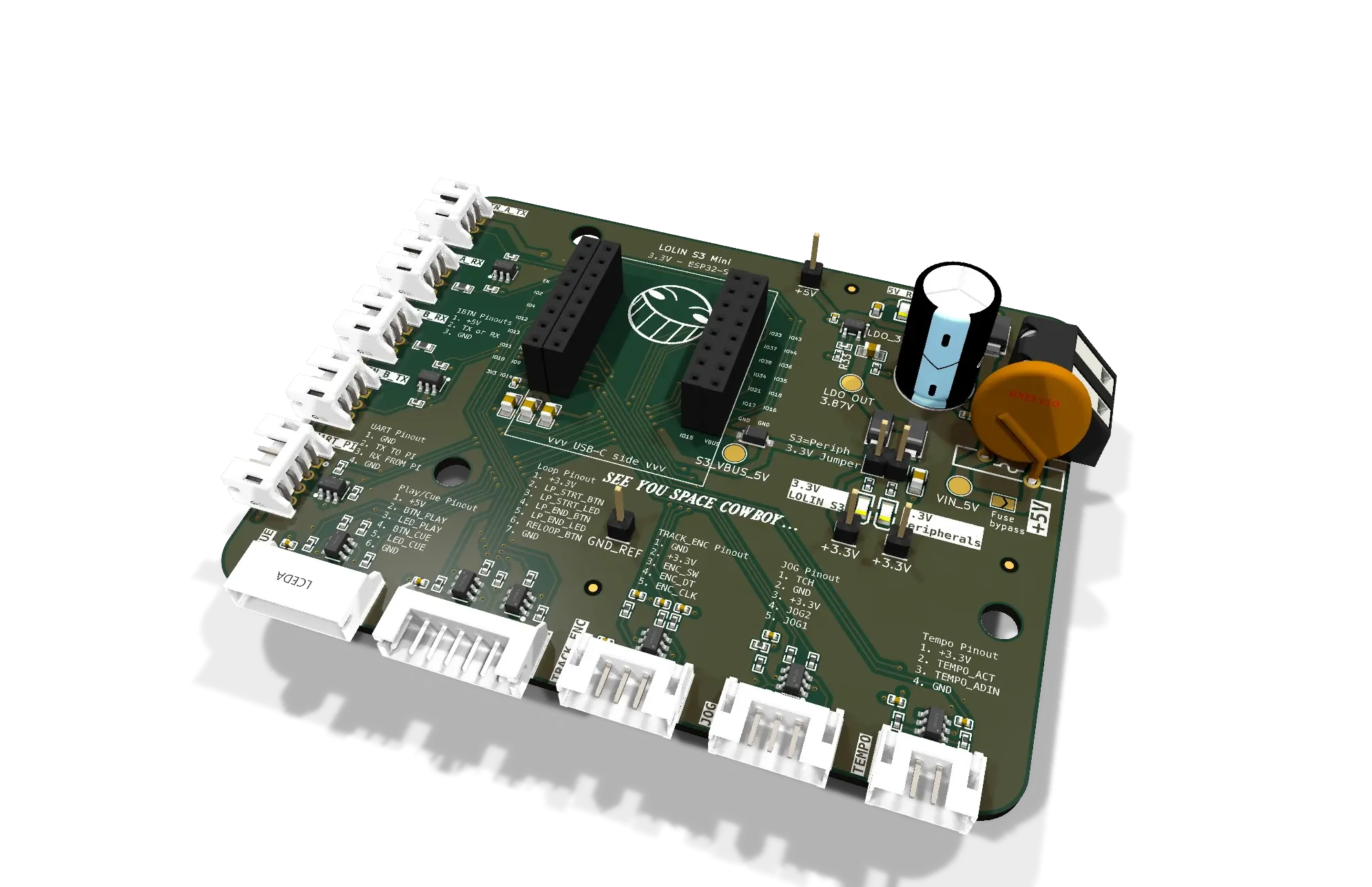
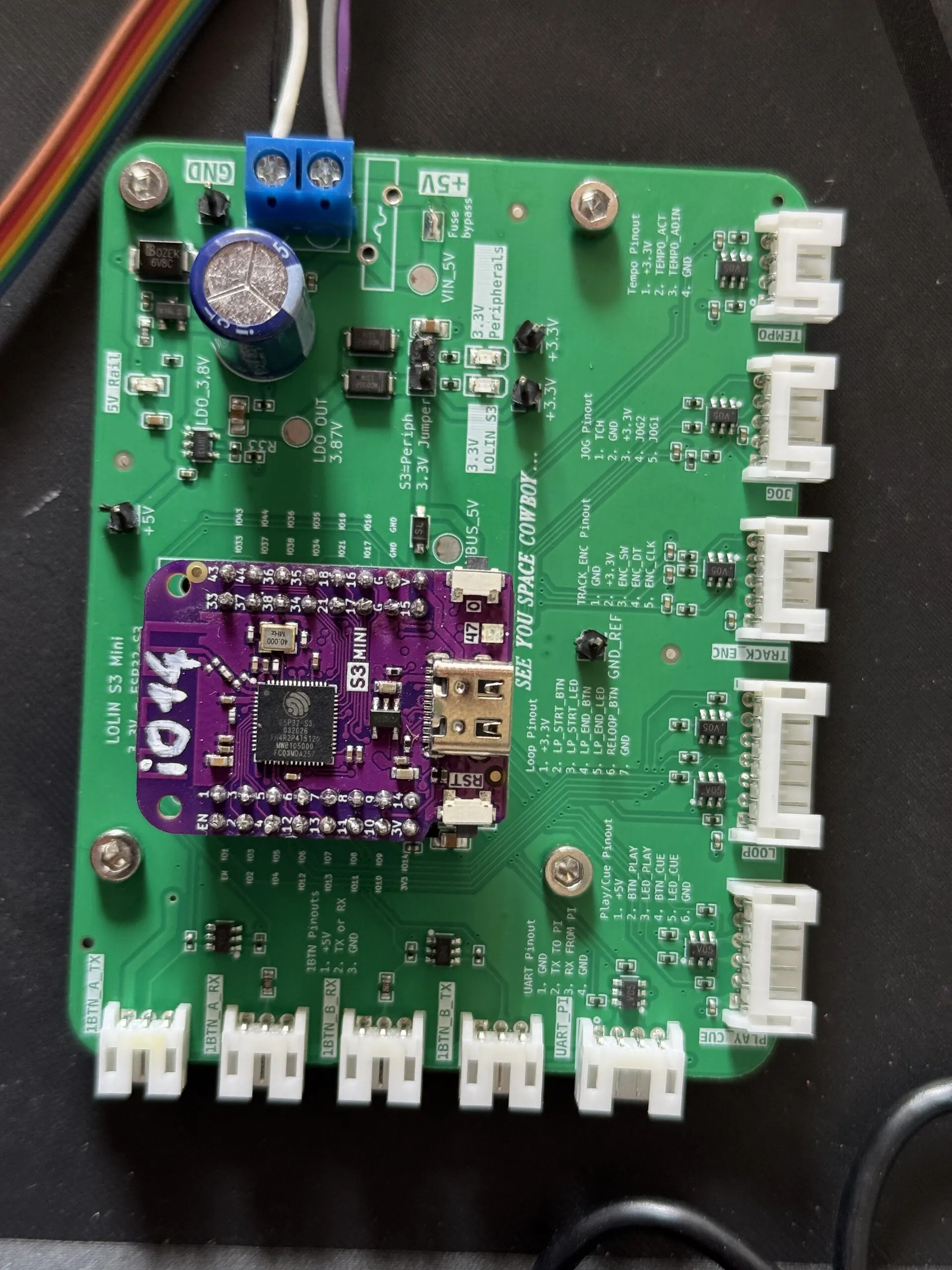
At the centre sits midi_s3_mini, a carrier board for a LOLIN S3 Mini. The ESP32-S3 on it has what reading a deck needs: a hardware pulse counter for the jog wheel, so no turn is ever missed and no interrupt ever fires; three UARTs; two cores; and enough analog inputs for the tempo fader. Everything the DJ touches is wired to it, and everything it reads leaves as MIDI for the Pi.
The pads: a ring of identical boards
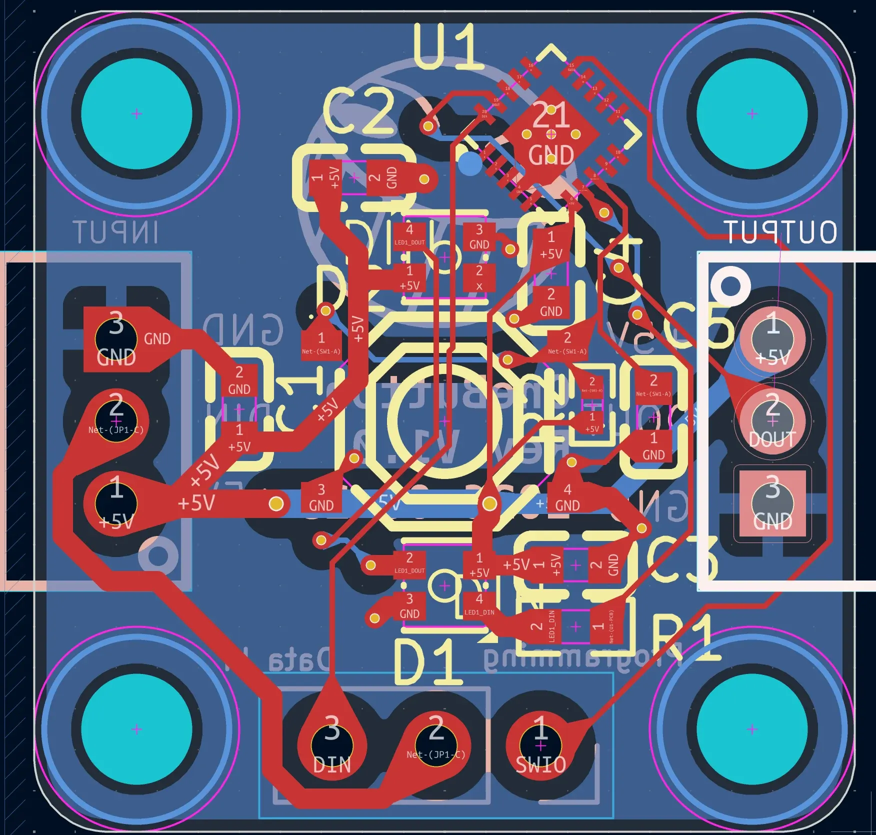
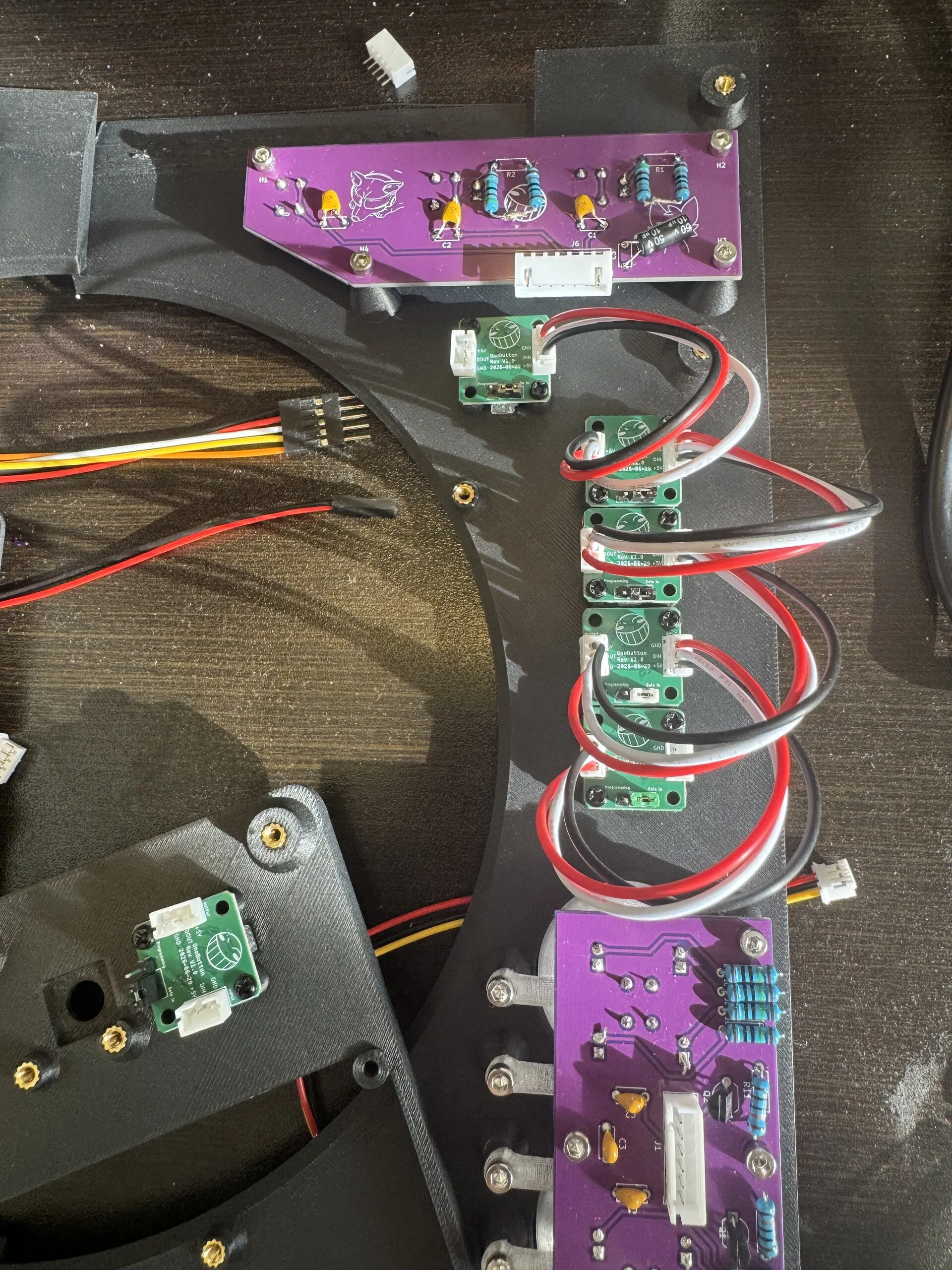
For the RGB pads, wiring each button and LED back to the S3 would have meant dozens of wires. Instead each pad is a OneButton node: a 20 mm board with a CH32V003, a 48 MHz RISC-V microcontroller that costs around ten cents, a switch and two RGB LEDs. Nodes daisy-chain into a ring over three-wire cables, and the ring has its own protocol, written up as a specification on 7 July.

The S3 sends one fixed-length frame into the ring. The frame carries the colour of every LED outward, and every node writes its button into its own slot as the frame passes through it, so when the frame comes back round, it carries every button on the ring.
Two choices make it fast and simple:
- Cut-through relaying. A node doesn’t wait for the whole frame: it forwards each byte the moment it arrives, editing only the byte that belongs to it. A frame’s trip round the ring costs one frame time plus one byte per node, rather than one frame per node.
- Positional addresses. At start-up the S3 sends an enumeration frame with a hop count of zero, and each node takes the count it receives as its index and passes on count + 1. Every node runs the same binary and needs no configuration, and a ring sizes itself to however many nodes it has.
Bring-up: why are the LEDs white?
The first node came up on 7 July with both LEDs white whatever colour was sent, and a button that seemed dead. Printing over the debug link showed the bytes arriving correctly, so the fault was in the timing of the LED signal, and the button was fine: a pressed pad turns magenta, which on a white LED that ignores its data looks exactly like nothing happening. One symptom, one cause.
The cause was the compiler. The LEDs’ protocol encodes each bit as a pulse whose length matters to a fraction of a microsecond, and the delay loop written in C had been reshaped by -Os -flto. The fix was a sled of NOP instructions, about 21 ns a step. Then came the margin: a “0” pulse worked anywhere from 0 to 16 steps and failed at 17, and since heat slows the chip’s oscillator and pushes the pulses towards that edge, it was set to 8. A node then held a minute at 150 °C without a glitch.
Tune to margin, not to “it works”.
The nodes are flashed over a single wire, SWIO. Rather than buy a programmer, a spare Arduino Pro Micro was turned into one, and porting its firmware from the Uno it was written for turned up a latent bug, a bit mask that cleared the wrong bit, whose fix is why flashing is reliable now.
The ring that never talked
With nodes working alone, two on a ring said nothing at all. The S3 was sending at 1 Mbaud and the nodes listening at 500 kbaud: two times apart, so not one byte made sense. With both ends at 500 kbaud, the S3 also learned to distrust a single enumeration: the count has to come back the same twice in a row before the ring is believed, and ten bad frames or a second of silence send it back to enumerating.
On 13 July the first two nodes ran on ring A. On 29 July ring B joined, on the S3’s third UART, and the deck greeted its own start-up with a rainbow wave running round both rings.
Version two, and the pin that kept dying
The first S3 board, ordered on 3 July, was all through-hole. It worked, but IO14, the pin for the jog’s touch switch, died on two boards. The notes are blunt about it: “I don’t want my pins dying. Again.” The suspect was the touch switch itself, a twenty-year-old membrane that might ring below ground when released, and a full oscilloscope procedure was written to catch it in the act.
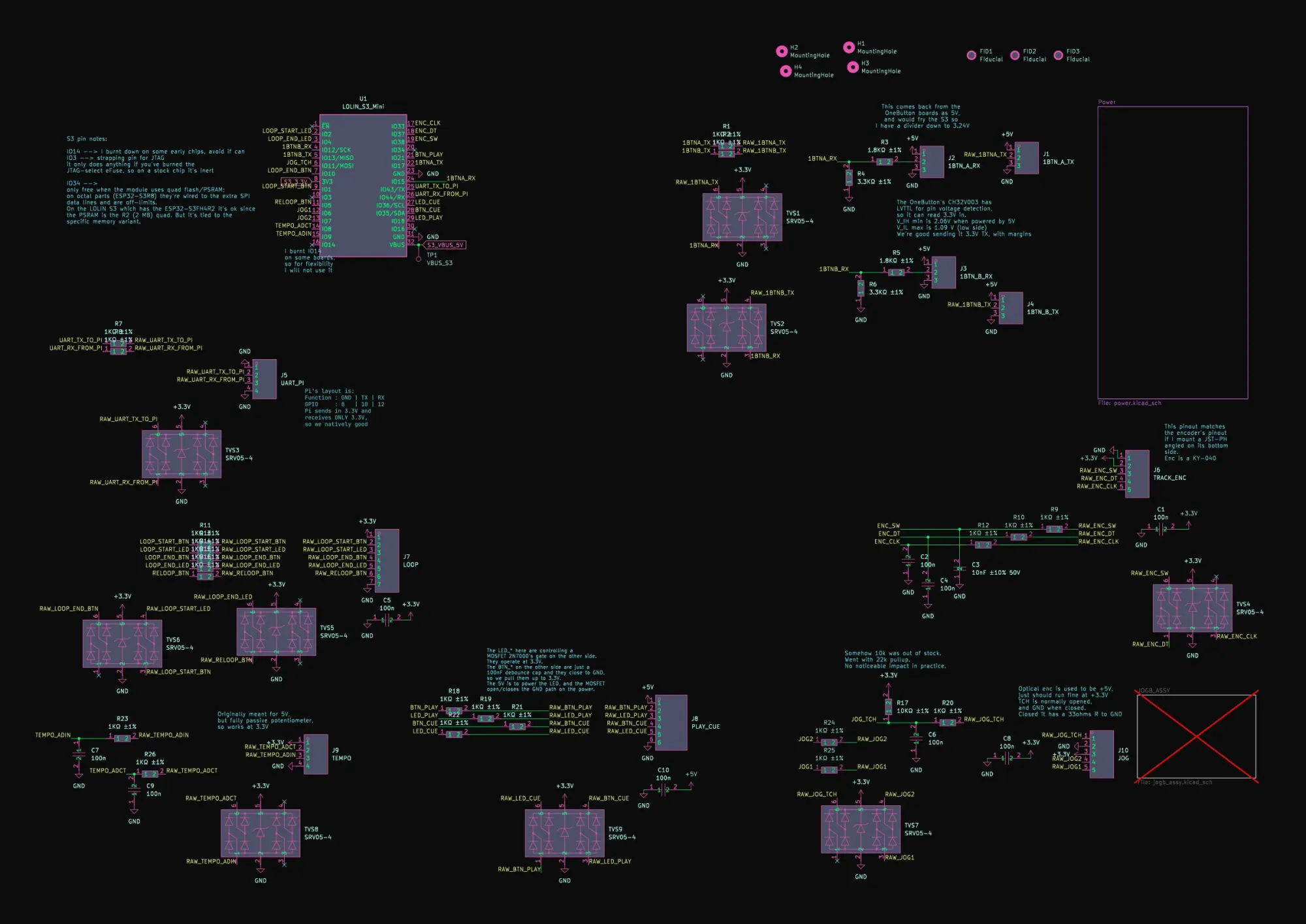
Version two didn’t wait for the verdict. Drawn on 21 and 22 July, it protects everything:
- an SRV05-4 TVS array on every input and output, and a 1 kΩ resistor in series with each;
- the touch switch moved from IO14 to IO11;
- reverse-polarity protection with a P-channel MOSFET, a soft start, a footprint for a polyfuse and 1000 µF of bulk capacitance;
- a regulator set to 3.87 V, so that after its diode the board’s own supply always wins over the USB port’s, and the S3’s regulator never sees reverse voltage;
- dividers bringing the rings’ 5 V replies down to 3.24 V, while the S3’s 3.3 V output is enough for the CH32V003, which reads a high from 2.06 V.
It was routed without a single break in the ground plane, passed DRC with no errors, and received some art on the silkscreen. At 01:43 on 23 July: “Finally fabbed v2”.
The other boards, and the firmware that ties them together
PLAY and CUE, and the three loop buttons, have no microcontroller: their switches and LEDs are wired straight to the S3. Each switch has a 100 nF capacitor, and a FreeRTOS task polls them every 2 ms, wants three stable samples before believing a change, and latches each press so a busy main loop can’t lose it.

The firmware grew a module per peripheral, and some of its numbers came from measuring rather than guessing. The jog’s disk, estimated in March at about 3,250 pulses a turn, measured exactly 12,960 counts: 3,240 lines, read in quadrature. The tempo fader’s centre tap turned out not to be centred, 1,944 counts from one end of the travel and 2,150 from the other, so each side got its own span. Moving the fader’s readings to their own task took the main loop from about 480 passes a second to about 98,000, and the jog now reports every 300 µs.
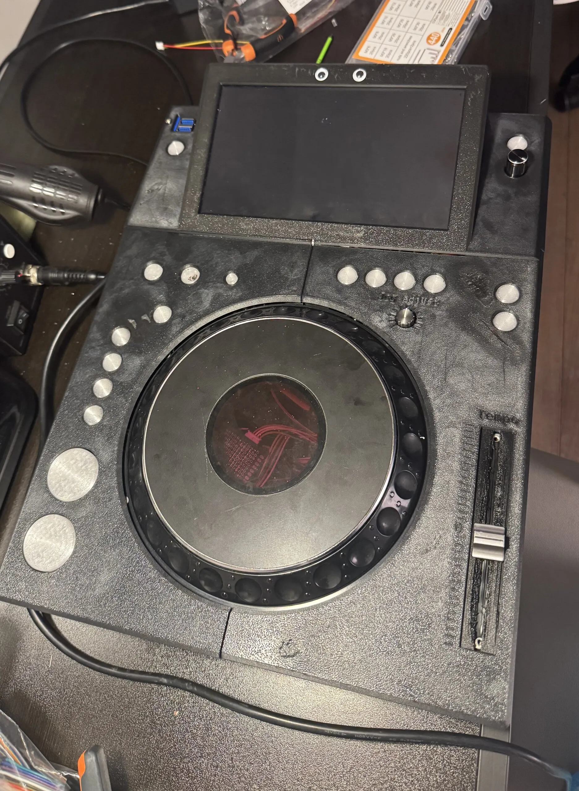
By the end of July the deck’s hands and eyes were done: every control read, every light driven, all of it arriving at the Pi as plain MIDI. What the Pi did with it is the next part.