Hardware

Boards you can order. A chassis you can print.

A Raspberry Pi 4 and a USB sound card do what computers and sound cards already do well. Everything a DJ touches goes through boards made for this deck: an ESP32-S3 controller, two rings of tiny RISC-V pad nodes, and plain boards for PLAY, CUE and the loops. All of them are KiCad projects in the repository.

Chassis V2

Shaped like a deck, printed at home.

Drawn in Fusion 360 around measurements of real decks, and printed in carbon-fibre PETG. The second version, from September 2026, sinks the deck to 85 mm, leans a 10.1″ DSI touchscreen back towards the DJ, and puts mains power, Ethernet and RCA on the rear.

Body
423 × 329 × 85 mm
Jog platter
210 mm, from a CDJ-1000MK3
Tempo travel
130 mm
Screen
10.1″, 1280 × 800, DSI
Rear
IEC mains, RJ45, RCA out and in
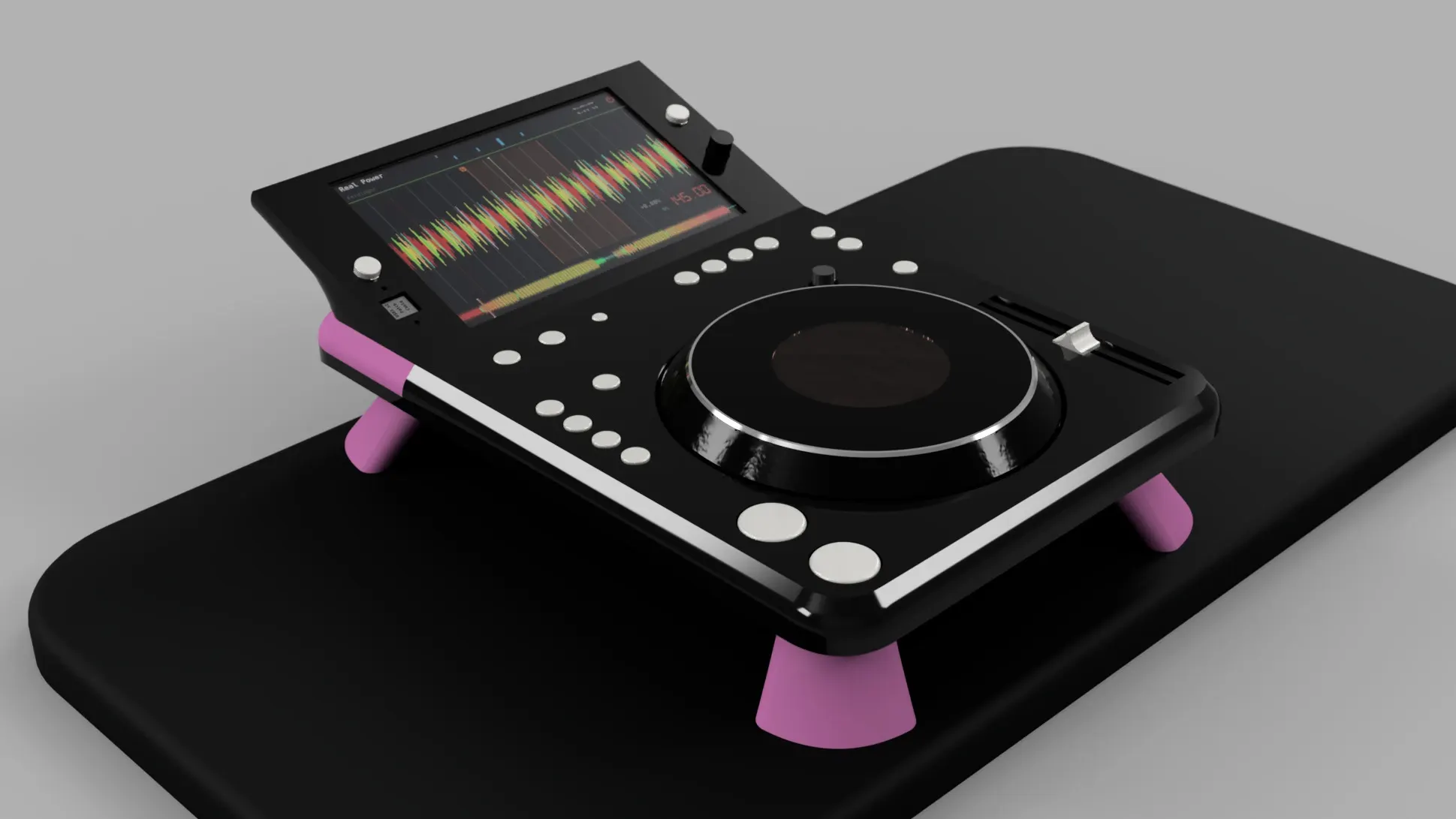
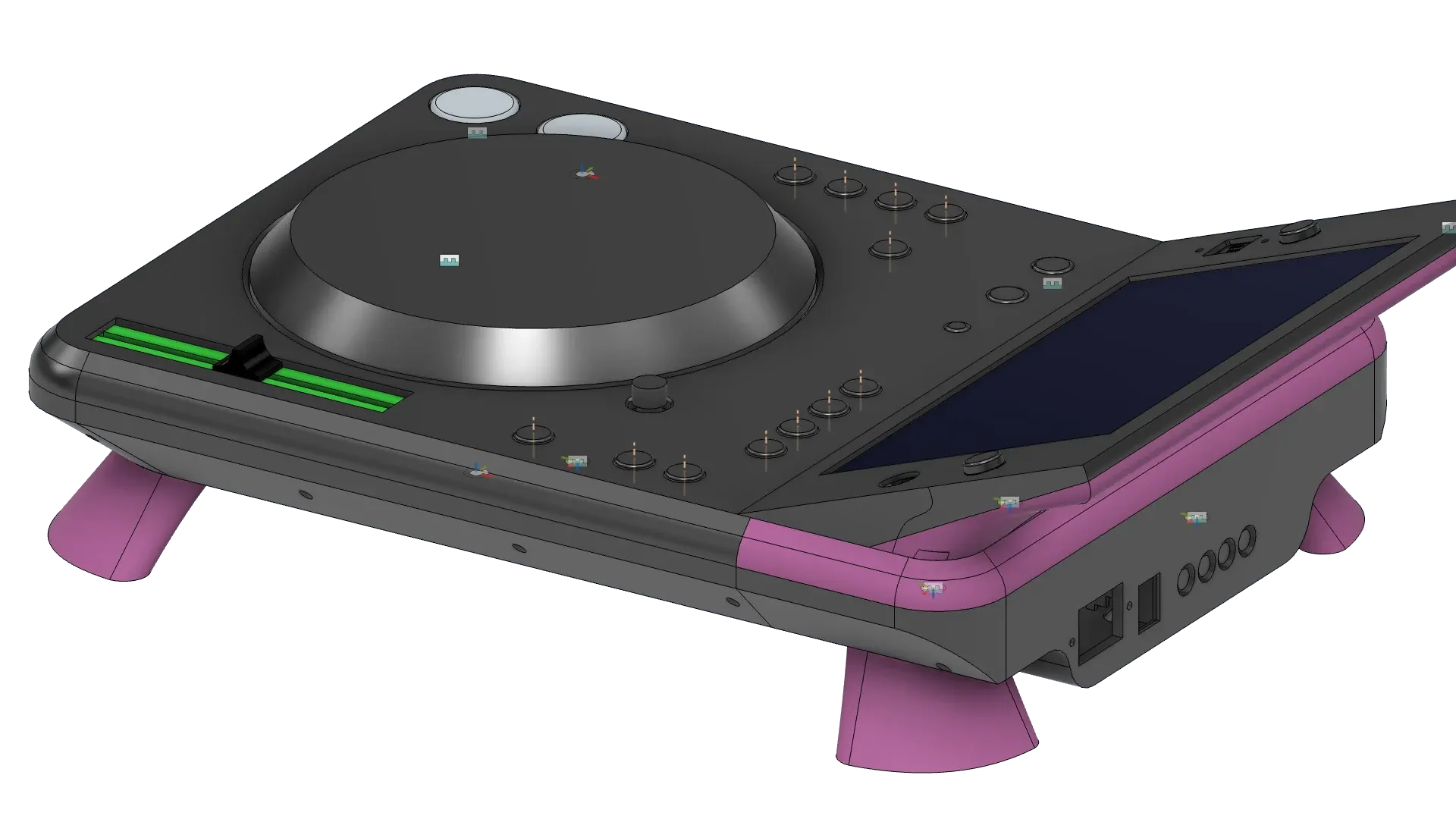
A render of the V2 chassis: black, on pink legs, with the screen angled up behind the jog wheel.
The V2 chassis, raytraced, September 2026.
The V2 chassis in Fusion 360, seen from the side: the fader slot lit green, the screen angled back, the rear panel with its sockets.
V2 in Fusion 360: the rear panel with mains, Ethernet and RCA.
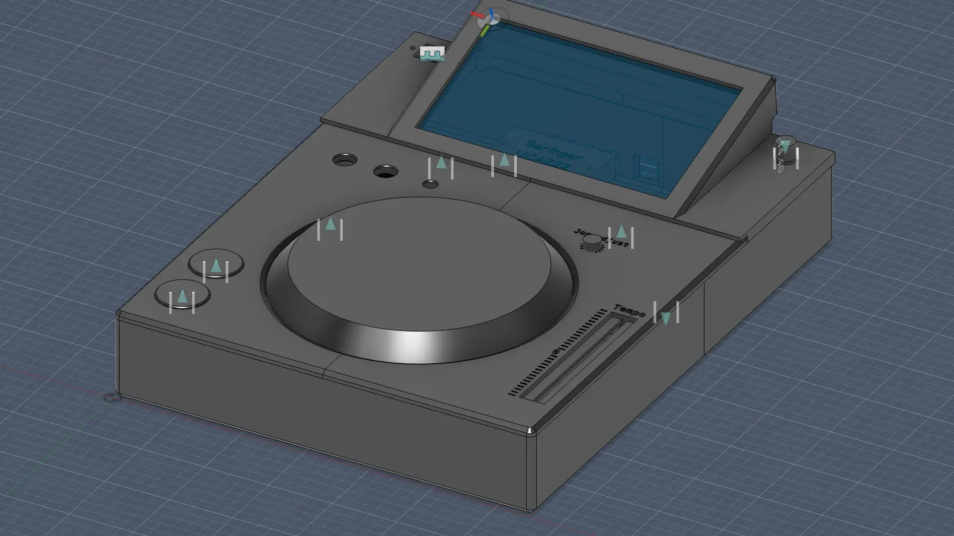
The V1 chassis in Fusion 360: a grey box with an angled screen housing, the jog wheel and the tempo fader slot.
V1, June 2026: a CDJ-3000's envelope, 453 × 329 × 118 mm.
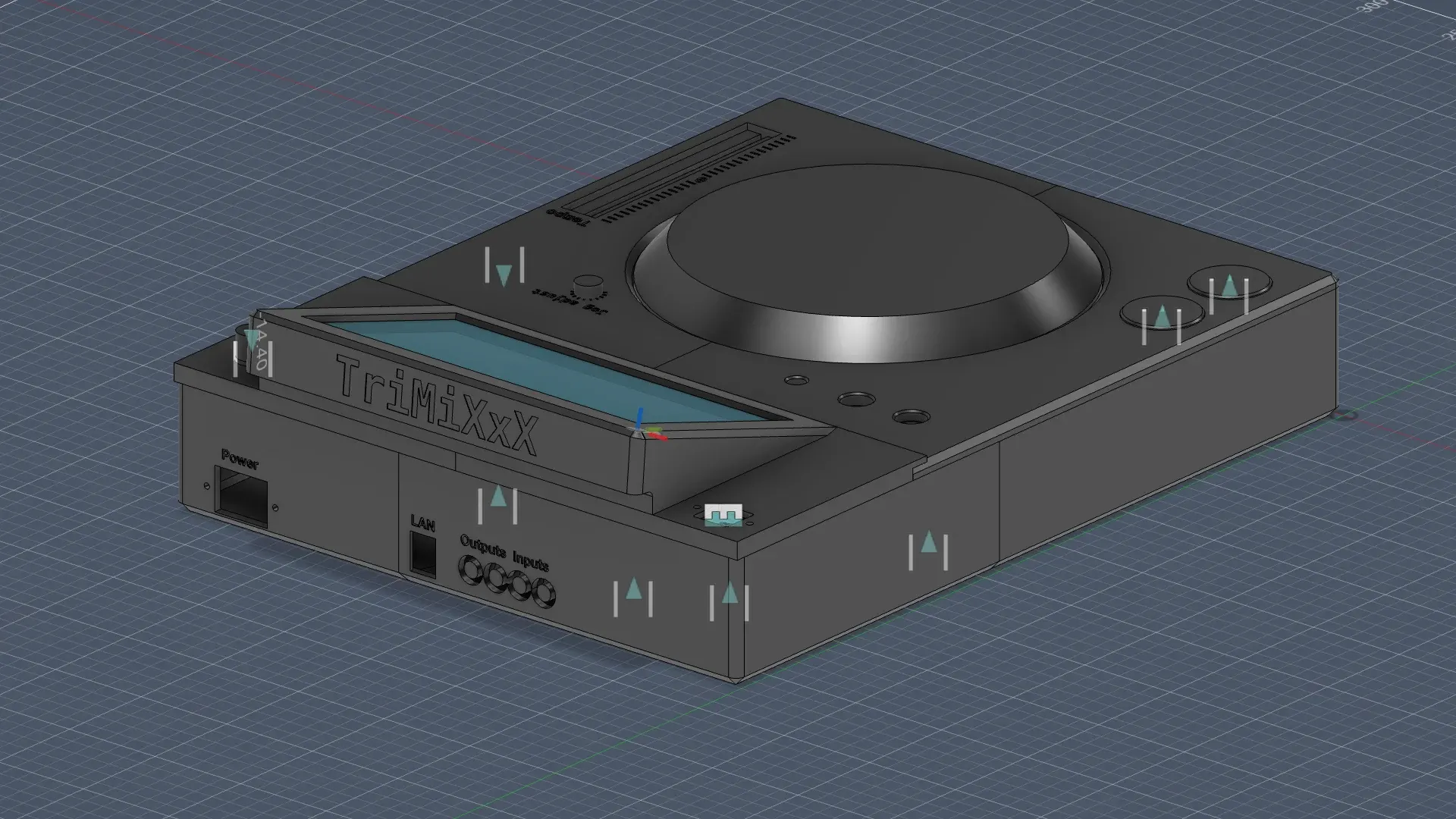
The back of the V1 chassis in Fusion 360, with cut-outs for power, Ethernet and audio.
V1 from behind: the sound card's outputs and inputs, power and LAN.
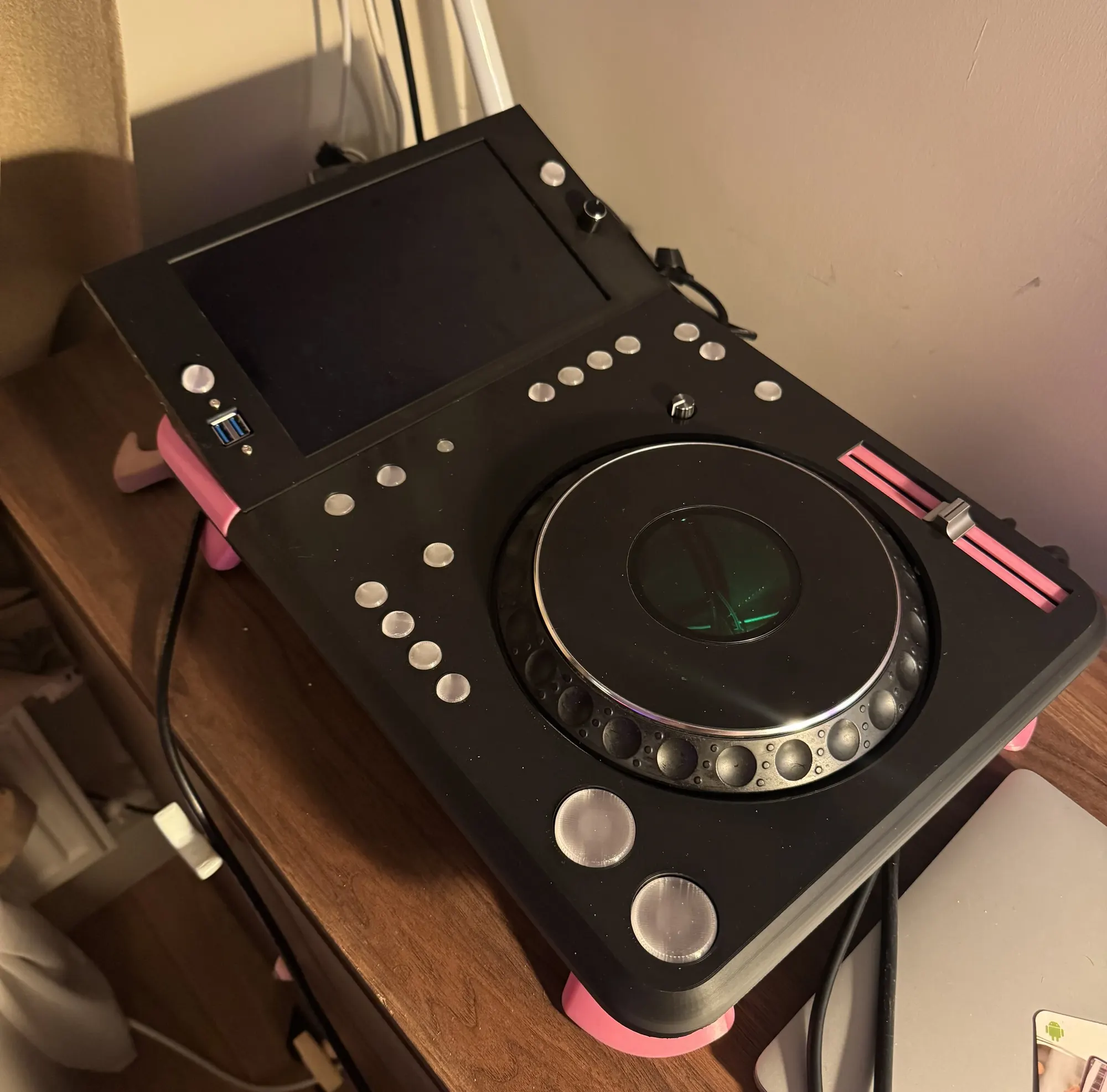
The deck seen from above at an angle on a wooden sideboard, screen off: a matte black printed top with rows of round silver buttons, a jog wheel glowing green at its centre, a tempo fader in a pink slot and a USB port beside the screen; pink feet lift it off the furniture.
trimixxx2, finished on 2 October 2026: the printed body, the CDJ-1000MK3 jog, the pink fader slot and legs.
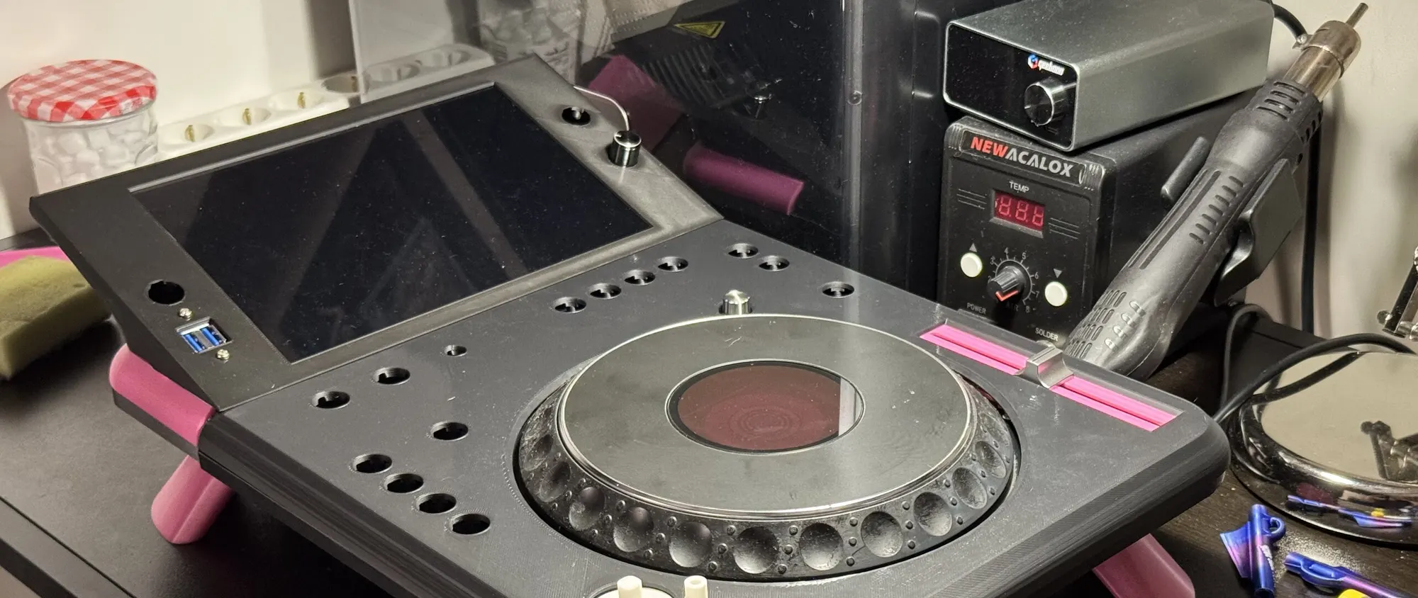
A black 3D-printed deck at an angle on a desk: a large tilted screen, empty round holes where buttons will go, a CDJ jog wheel, a pink inlay around the tempo fader slot and pink cone-shaped legs; a soldering station and a hot-air gun behind.
The V2 body on 17 September 2026, printed and assembled, before its buttons went in.
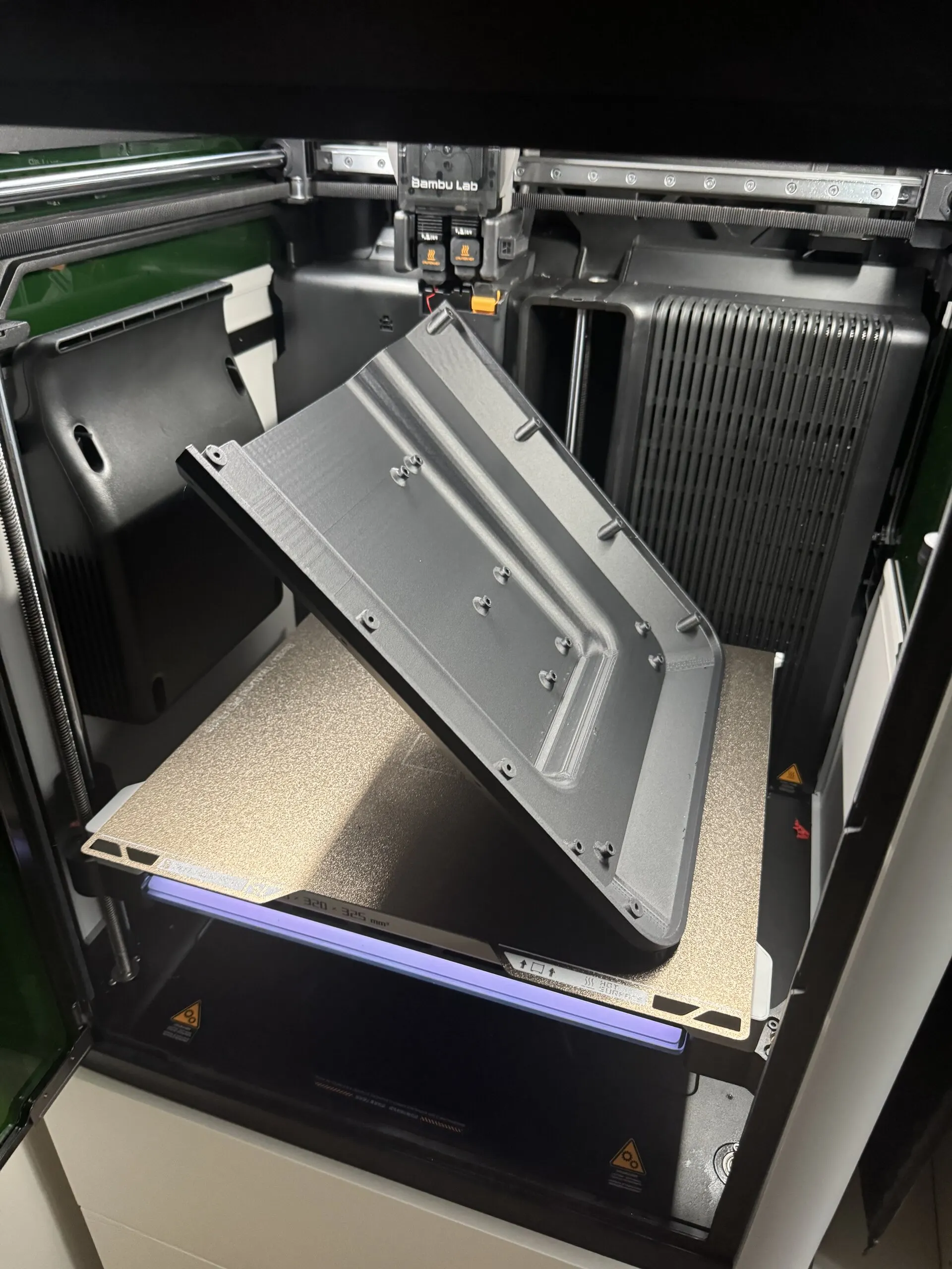
Inside a 3D printer, a large black ribbed panel with screw bosses stands at an angle on the textured build plate, the toolhead above it.
A V2 body panel printing on the Bambu Lab H2D, 9 September 2026.
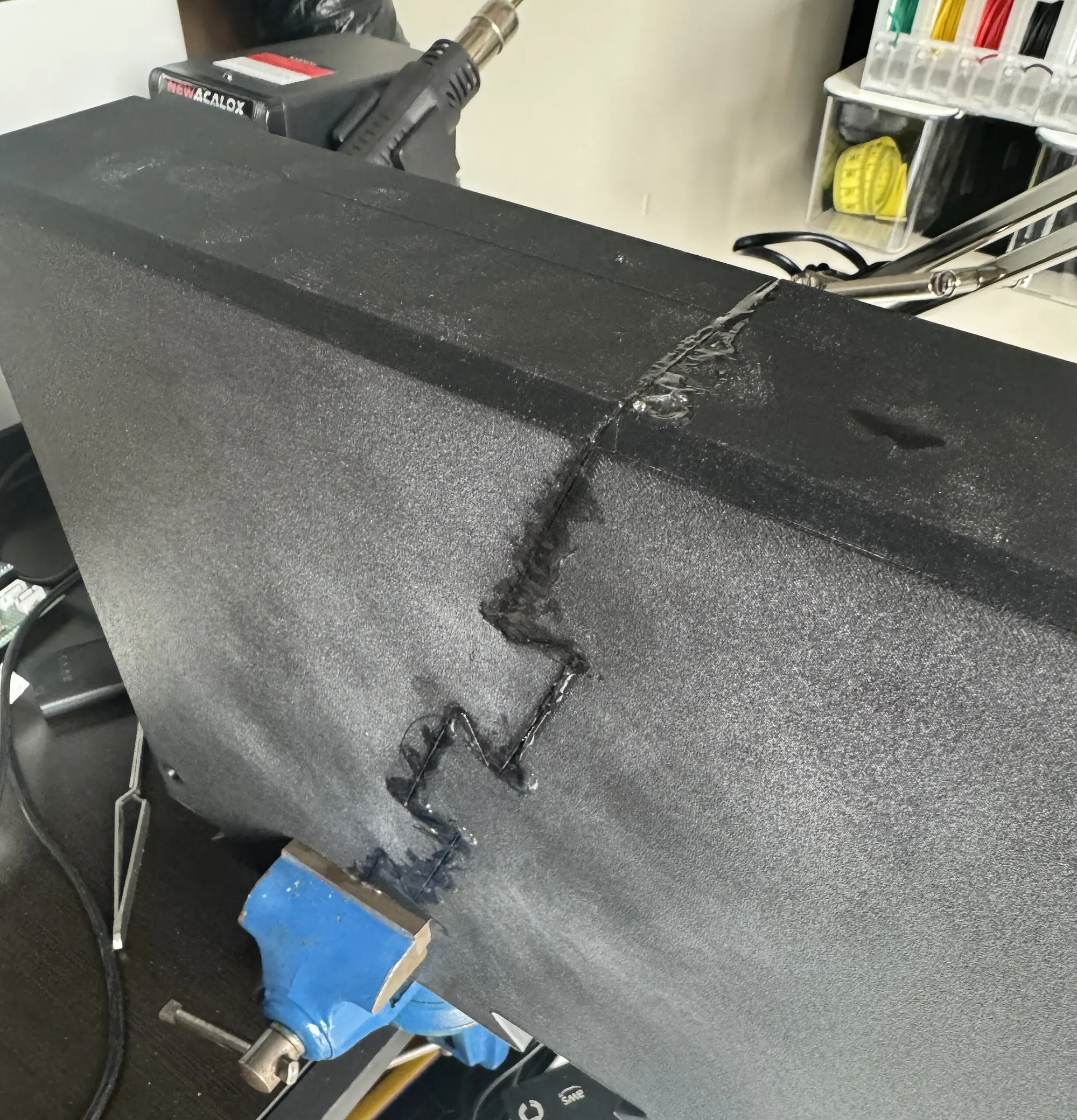
A large black textured printed panel clamped in a blue vise; a jagged, puzzle-shaped seam runs across it, filled with melted black plastic.
Two printed halves of a V1 panel, joined on a zig-zag seam and welded with melted plastic, 3 June 2026.
The boards

Six boards, four in the deck.

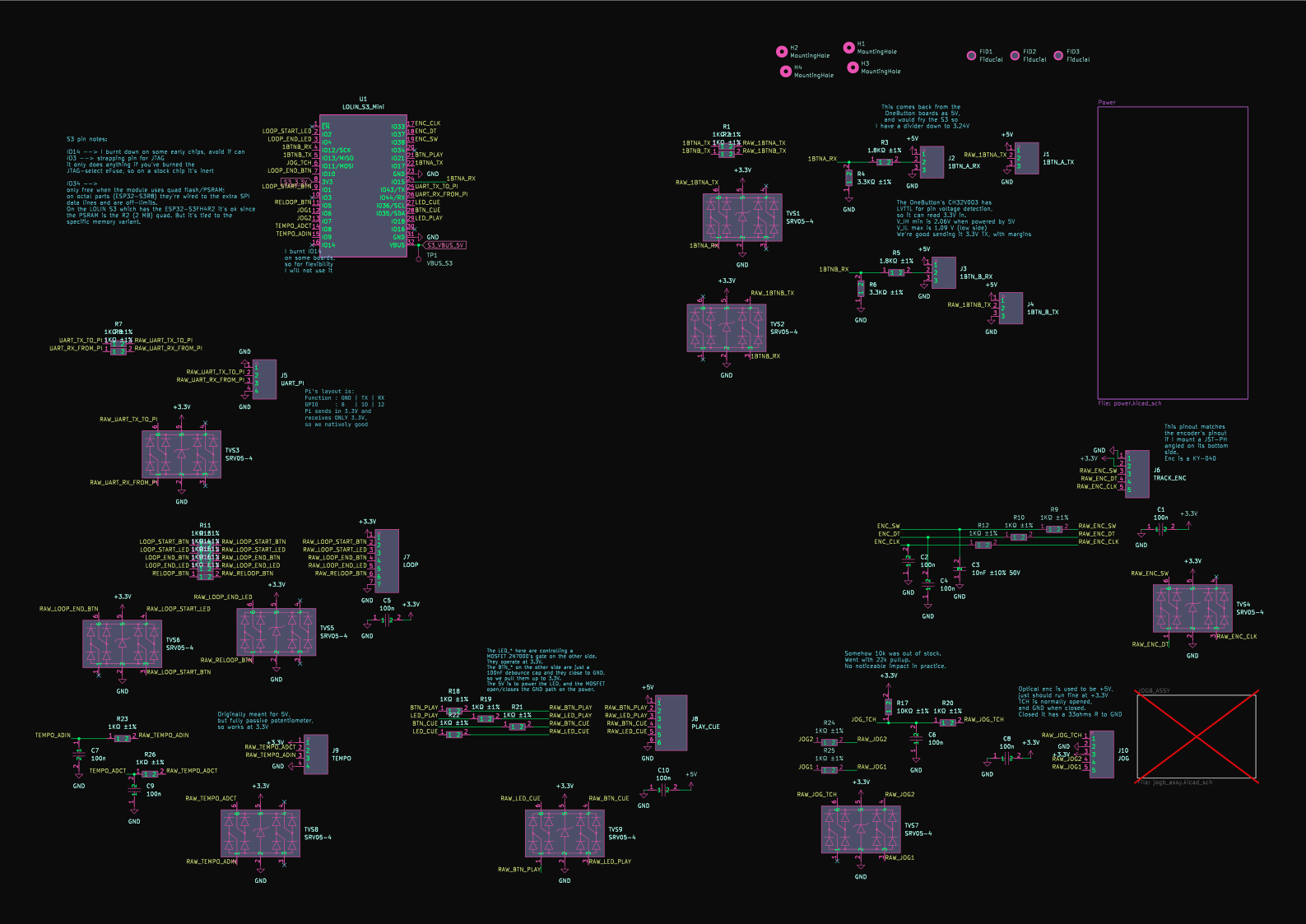
Rendered from their KiCad sources: click one to turn it in 3D. Each schematic opens as a vector drawing you can zoom into, notes in the margins included.

A 3D render of the midi_s3_mini board: a green PCB with headers for the LOLIN S3 Mini, a row of white JST connectors along two edges, a large capacitor and a screw terminal.
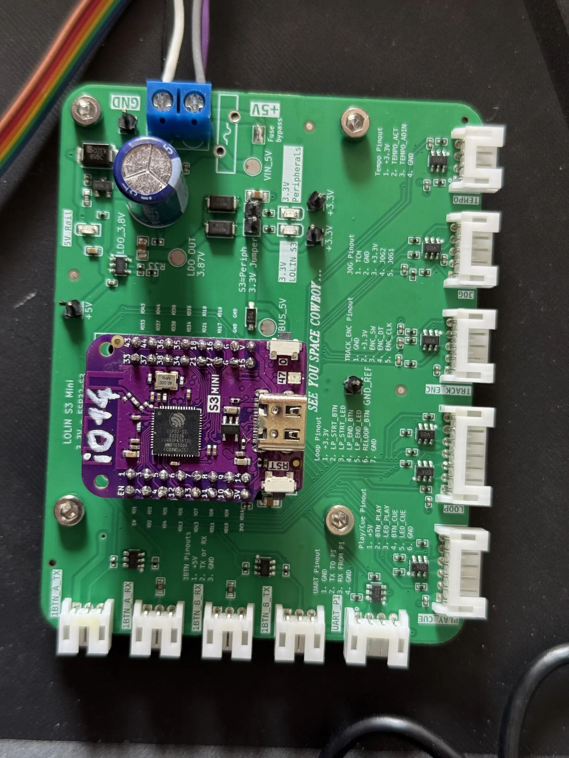
A green board with a purple ESP32-S3 module in the centre, a blue screw terminal for 5 V, and white connectors along two edges labelled for the two rings, the Pi's UART, the tempo fader, the jog, the encoder, and the loop and play/cue boards.
midi_s3_mini v2, the controller board, with its LOLIN S3 Mini, 28 July 2026.

midi_s3_mini

current

The controller. Every control on the deck lands here, and MIDI leaves for the Pi.

  • LOLIN S3 Mini (ESP32-S3) on headers, 90 × 70 mm, two layers
  • SRV05-4 TVS arrays and 1 kΩ series resistors on every input
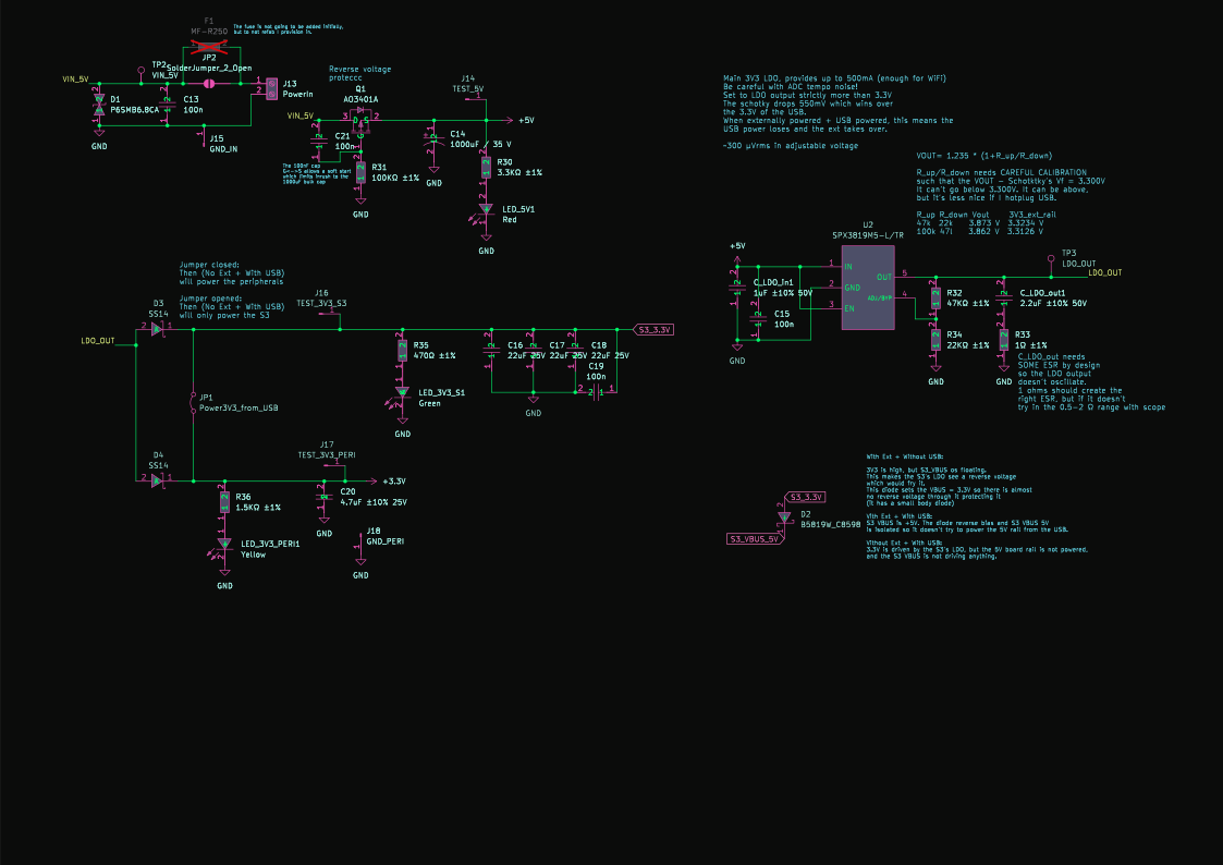
  • Reverse-polarity P-FET, soft start, a polyfuse footprint and a 1000 µF bulk cap
  • An LDO set to 3.87 V so the board's supply wins over USB, and the USB side held off
  • Dividers bring the rings' 5 V replies down to 3.24 V for the S3
  • v2, fabbed 23 July 2026; silkscreen: “SEE YOU SPACE COWBOY…”
A 3D render of the OneButton board: a small square green PCB with a tact switch in the middle, two LEDs beside it, a tiny QFN chip and JST connectors on two sides.
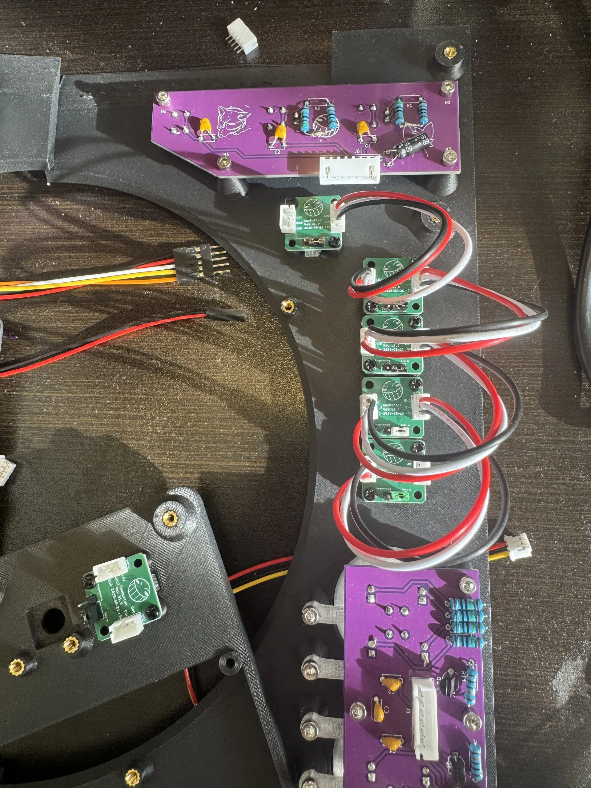
Inside the printed top plate: a purple board at the top, five small square green boards chained by red, white and black wires down the middle, and a second purple board at the bottom.
OneButton nodes chained between the loop board, at the top, and the play/cue board, 28 July 2026.

one_button

current

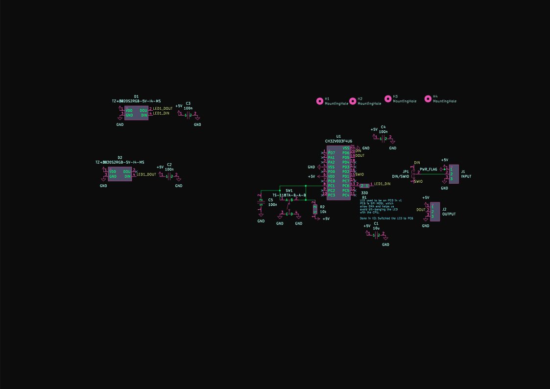
A ring node: one pad, two RGB LEDs, one RISC-V microcontroller. Every node is identical.

  • CH32V003F4U6, a 48 MHz RISC-V microcontroller in a 3 × 3 mm QFN
  • Two 2020-size RGB LEDs on the WS2812 protocol, and a tact switch
  • 20 × 20 mm; JST-PH in and out, so nodes daisy-chain into a ring
  • Relays the ring's frame byte by byte inside its UART interrupt
  • One binary for every node; its address comes from its place in the ring
  • Assembled by JLCPCB; flashed over one wire (SWIO)
A 3D render of the play/cue board: a bare copper PCB with two tact switches, each surrounded by four red 5 mm LEDs.
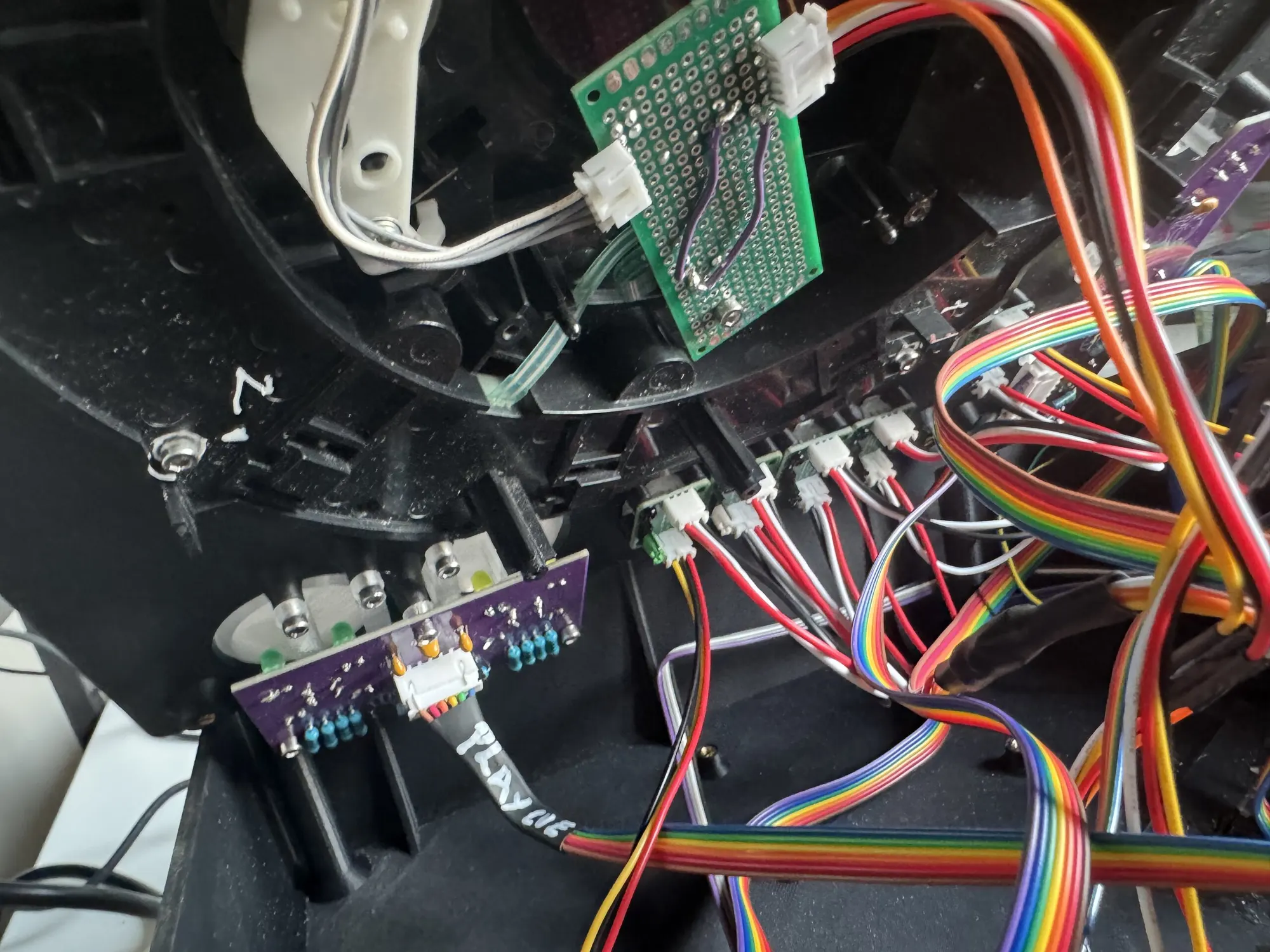
A purple board with blue resistors and a white connector whose cable is marked PLAY CUE in white pen, under two large buttons; above it, a perfboard with purple jumper wires links the jog's sensor.
The play/cue board under the CUE and PLAY buttons, its cable labelled by hand.

play_cue_btn

current

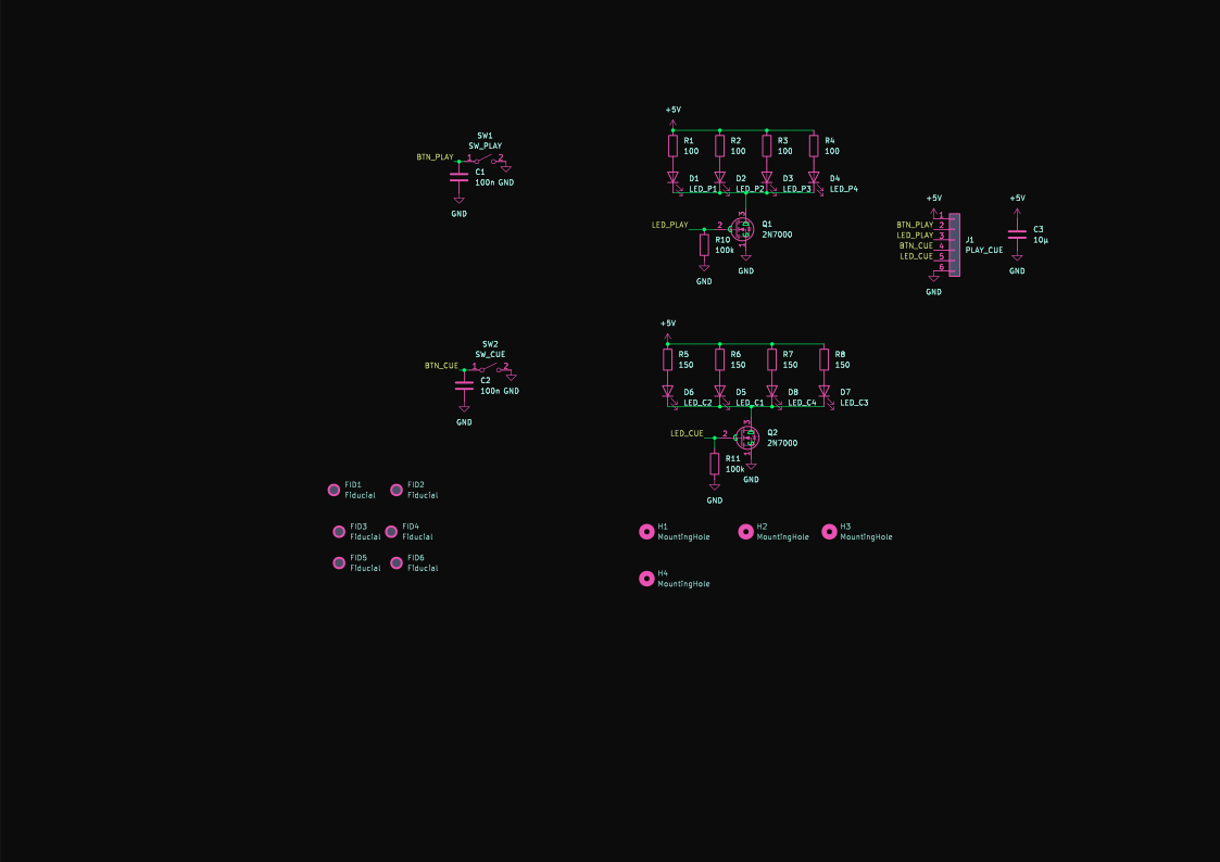
PLAY and CUE, each ringed by four LEDs that Mixxx lights.

  • No microcontroller: the S3 reads the switches and drives the LEDs
  • Eight 5 mm LEDs, switched from 5 V by two 2N7000 MOSFETs
  • 100 nF on each switch, so the edge is slow and clean for the poller
  • Laid out for a home etch: no vias, wide tracks
A 3D render of the loop board: a long bare copper PCB with three tact switches and two LEDs.

loop_btn

current

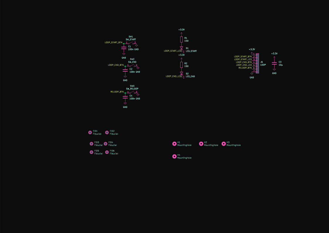
LOOP IN, LOOP OUT and RELOOP, under the jog wheel.

  • Three switches and two LEDs; RELOOP has no light of its own
  • LEDs sunk straight into the S3's GPIOs
  • No microcontroller and no vias, like play/cue
A 3D render of the midi-laser board: a green PCB with an Arduino Pro Micro footprint, a DIP-28 expander and JST connectors.
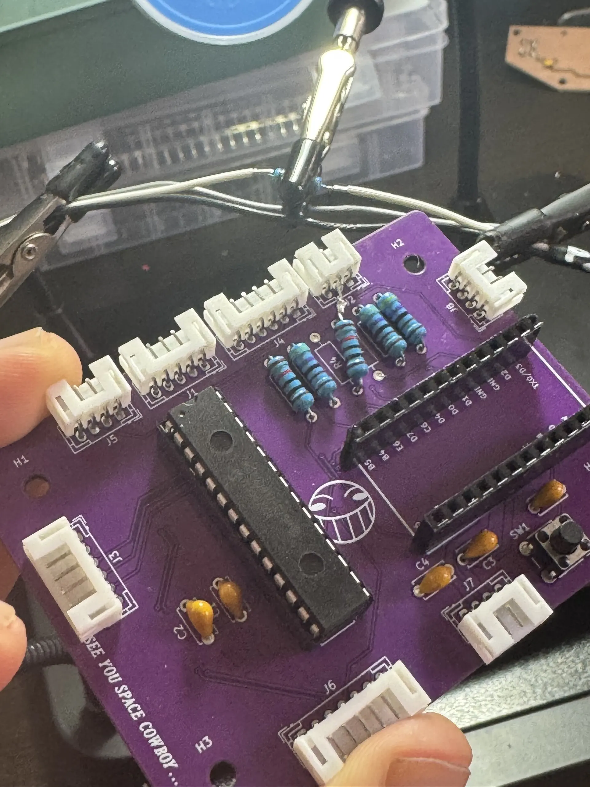
A purple board held between fingers: a long 28-pin chip, two rows of header sockets for a microcontroller, blue resistors, white connectors along its edges and a laughing-face logo.
The midi-laser board, made for an Arduino Pro Micro, back from the fab on 25 June 2026.

midi-laser-pcb

abandoned

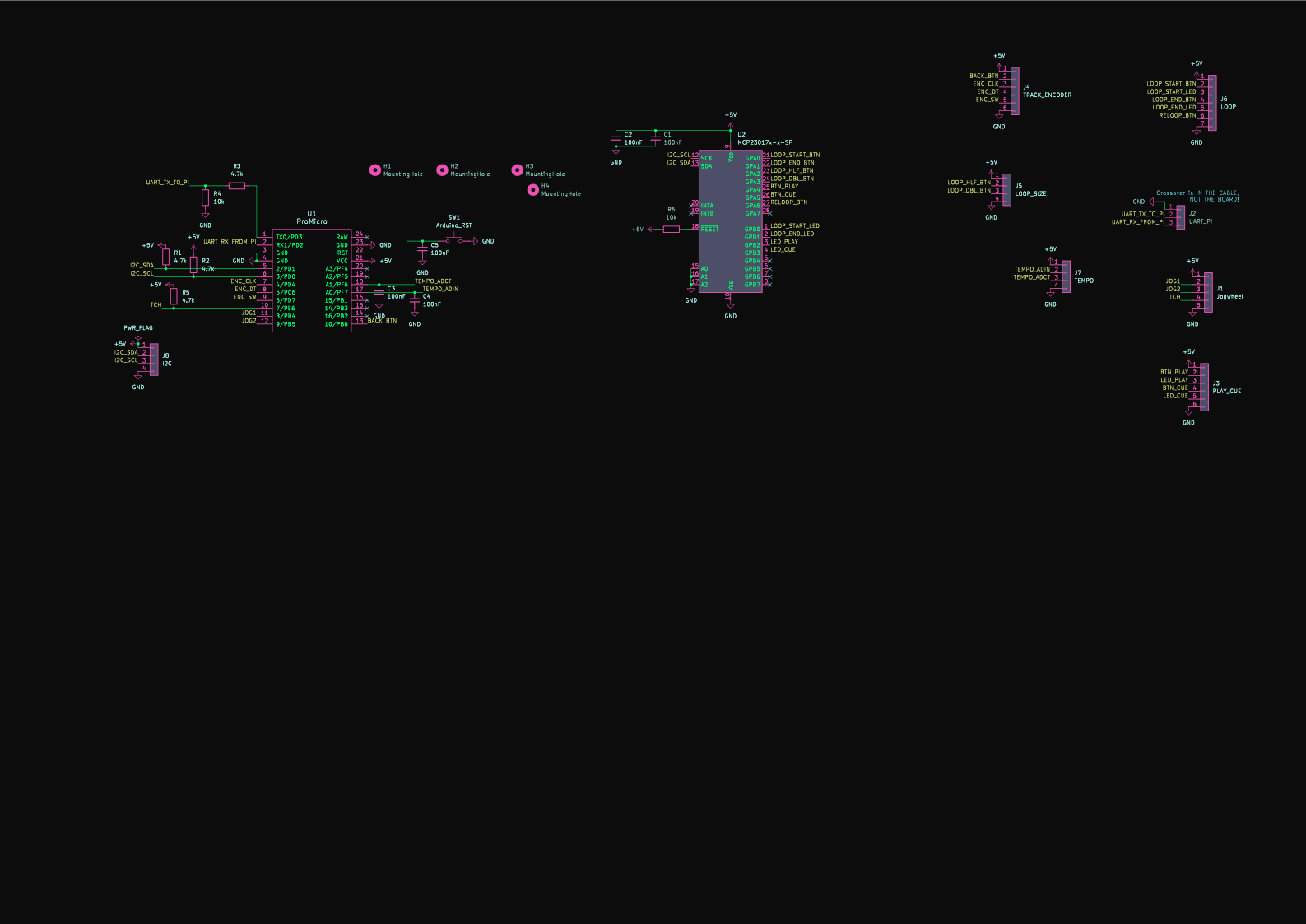
The first standalone controller, May 2026: a Pro Micro and an I²C expander.

  • Arduino Pro Micro (ATmega32U4) and an MCP23017 on I²C, 80 × 60 mm
  • Its bring-up list: no pinouts on the silkscreen, a divider on RX that belonged on TX, and RELOOP left off the expander
  • Its bring-up and the ESP32-S3 board's design happened on the same day, 30 June
KiCad's 3D view of the monolithic main board: a long green PCB with RCA jacks, USB ports and the Compute Module 5.

CDJ-MainBoard

never built

The monolithic first design, Feb – Mar 2026: everything on one board.

  • Compute Module 5, PCM5122 DAC, USB-C PD at 20 V, an ATmega32U4 MIDI controller
  • 250 × 104 mm, four layers, 210 footprints, 406 vias
  • Fully routed on 26 March 2026; removed in July, kept in the history
Inside

Open it up.

Under the top plate: the CDJ's jog mechanism, the chain of pad nodes, the play/cue and loop boards, and the wiring back to the controller. Under the screen: the Pi, the controller board and the power supply.

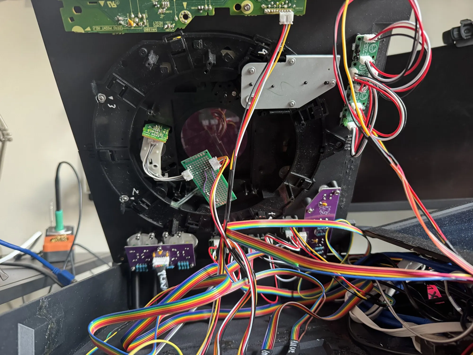
The underside of the top plate, opened like a lid: the black frame and metal bracket of a CDJ jog wheel with a small sensor board, a column of small green button boards linked by red and white wires, two purple boards, and bundles of rainbow ribbon cable.
trimixxx1 opened up: the CDJ-1000MK3 jog mechanism, the pad nodes and their cables, 11 August 2026.
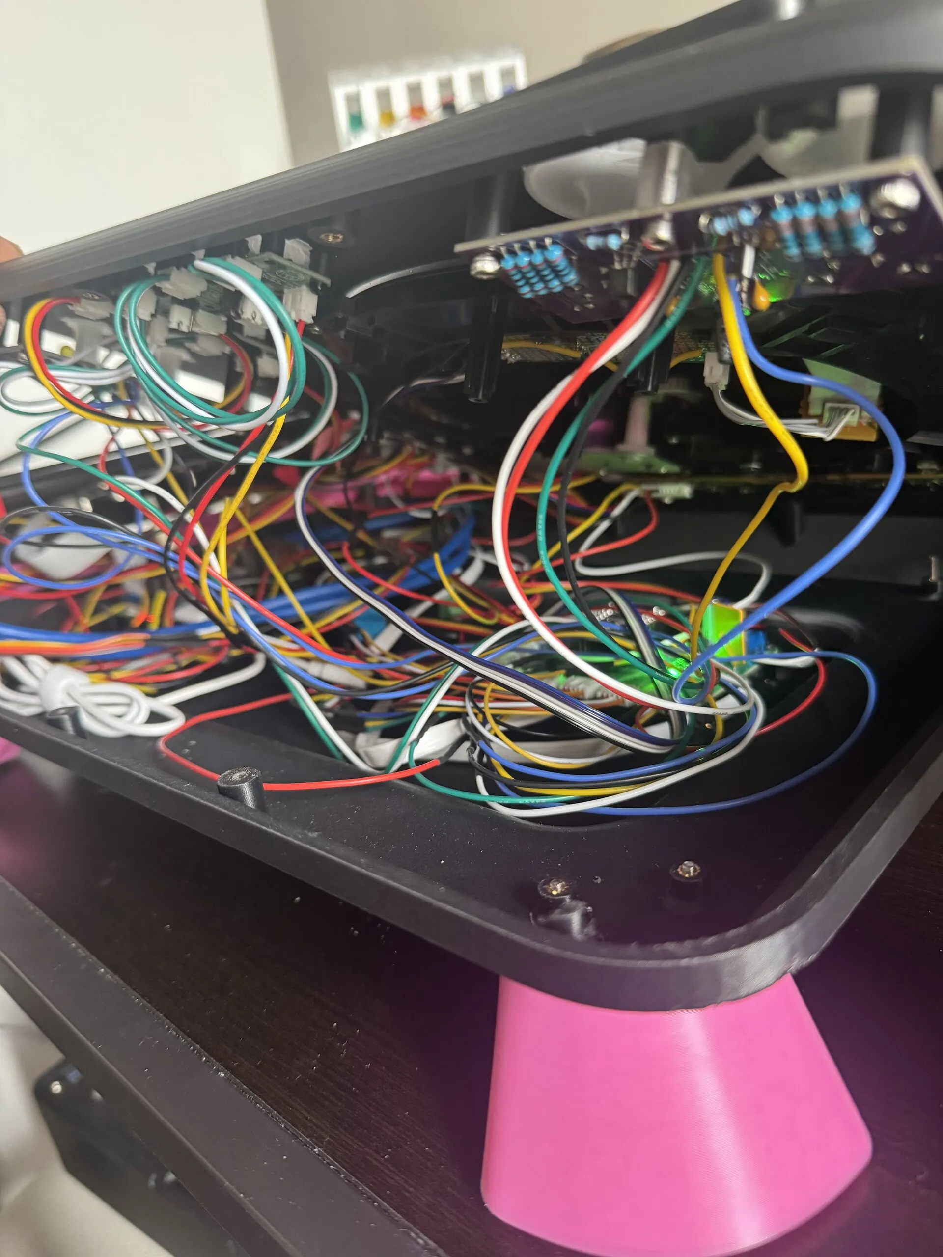
The deck's top tilted up to show its underside: a dense tangle of red, yellow, blue, green, black and white wires between purple boards and connectors, with a pink leg at the bottom.
Inside trimixxx2: the wiring between the button boards and the controller, 10 October 2026.
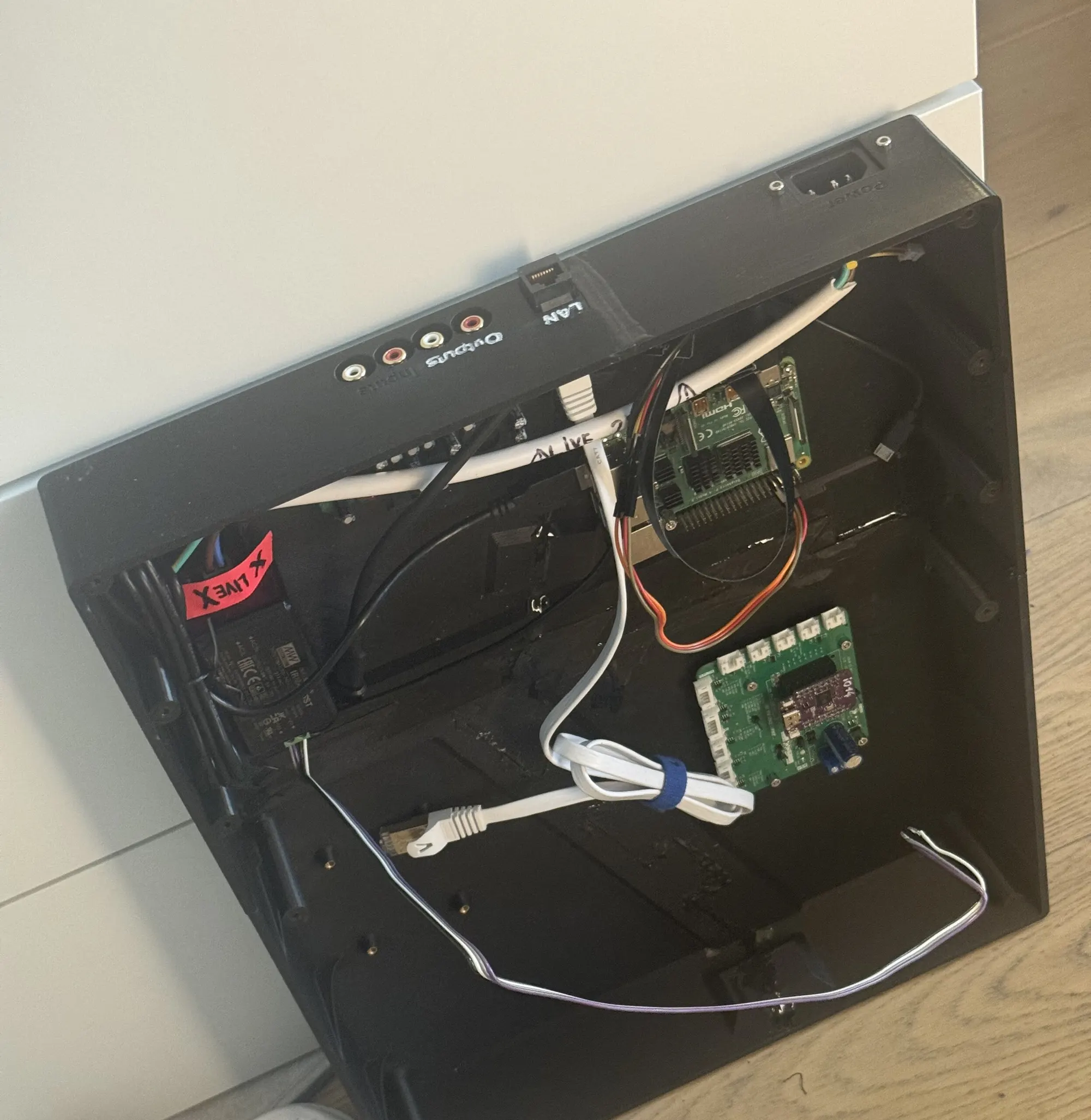
Looking into an open black printed tray: a Raspberry Pi 4, the green controller board with its purple module, a power supply, and cables to a rear panel with RCA outputs, a network port and a mains inlet.
The V1 base: a Raspberry Pi 4, the controller board, the power supply and the rear connectors, 28 July 2026.
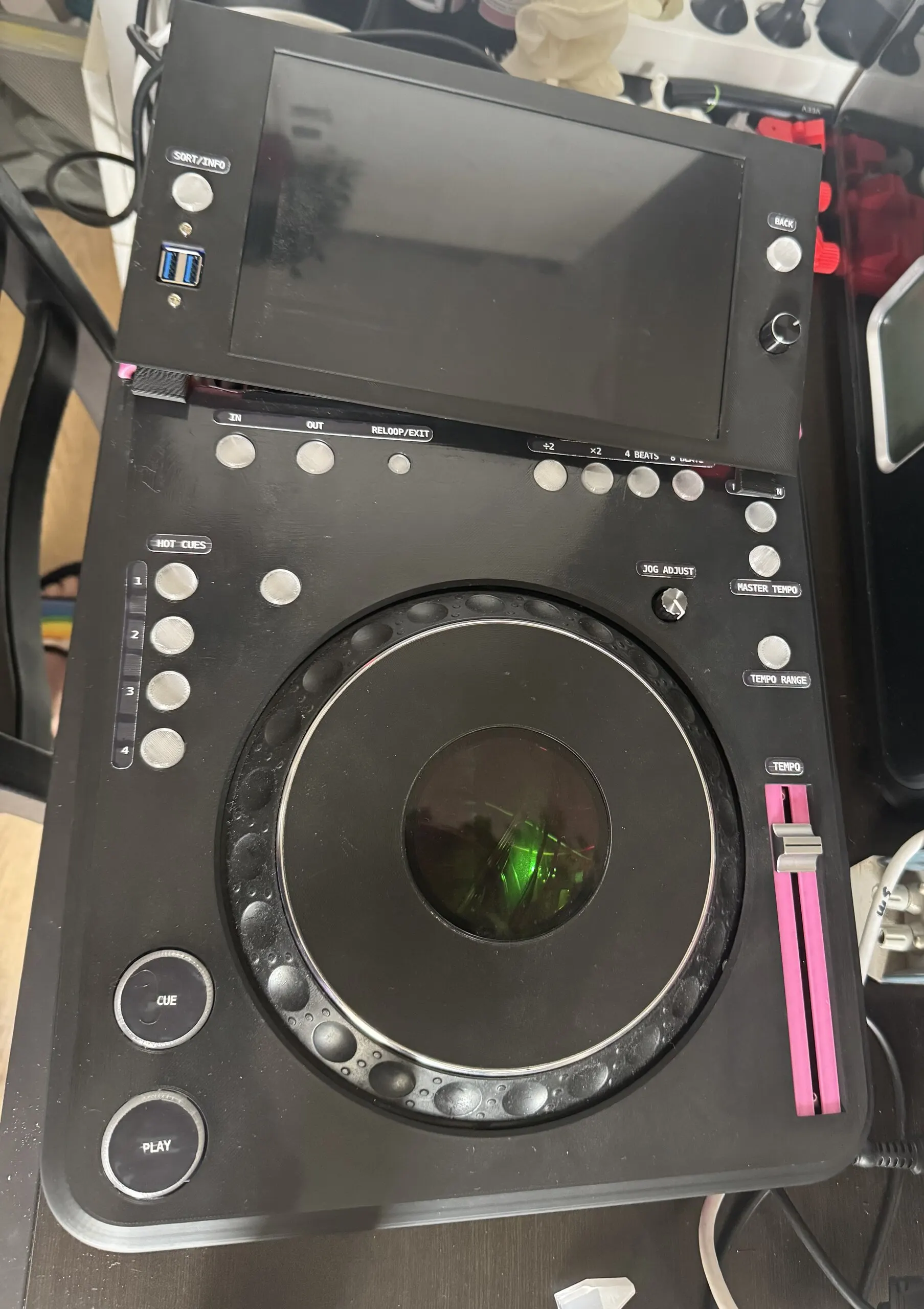
Top-down view of the deck with printed labels: SORT/INFO and BACK by the screen, IN, OUT and RELOOP/EXIT along the top, the beat-loop sizes, HOT CUES 1 to 4 down the left, JOG ADJUST, MASTER TEMPO and TEMPO RANGE on the right, a TEMPO fader in a pink slot, and CUE and PLAY at the bottom left. The screen is off.
trimixxx2's top plate and its printed labels, 10 October 2026.
Parts

What's inside a deck.

The second deck as built in October 2026. The jog wheel, and probably the fader, came out of a Pioneer CDJ-1000MK3; the buttons are new switches under printed caps.

PartWhatNotes
ComputerRaspberry Pi 4 Model B, 4 GBRuns Raspberry Pi OS, Mixxx and the deck's services
ScreenWaveshare 10.1″ DSI LCD (C), 1280 × 800, touchThe first deck has a 1024 × 600 touchscreen behind a lip
SoundBehringer UCA222 (TI PCM2902)RCA out to the mixer; RCA in for Record set
ControllerLOLIN S3 Mini (ESP32-S3)On midi_s3_mini
PadsCH32V003F4U6 + 2 × RGB LED per nodeTwo rings: 7 + 6 nodes on the first deck
Jog wheelA CDJ-1000MK3 jog assemblySharp GP1A038RBK optical sensor on a 3,240-line disk: 12,960 counts a turn; a touch switch in the platter
TempoCentre-tapped slide potentiometerRead ratiometrically, sent as 14-bit MIDI
BrowseKY-040 push encoderDecoded with a state table, one tick per detent
Buttons6 mm tact switches under printed capsWith 5 mm LEDs on play/cue and loop
PowerIEC mains inlet and a 5 V, 30 W module (IRM-30-5ST)In the V2 chassis; passively cooled
NetworkRJ45 panel couplereth0 for Pro DJ Link; Wi-Fi for everything else
ChassisPETG-CF, printedV2: 423 × 329 × 85 mm
Made at home first

Etched with a laser before ordering.

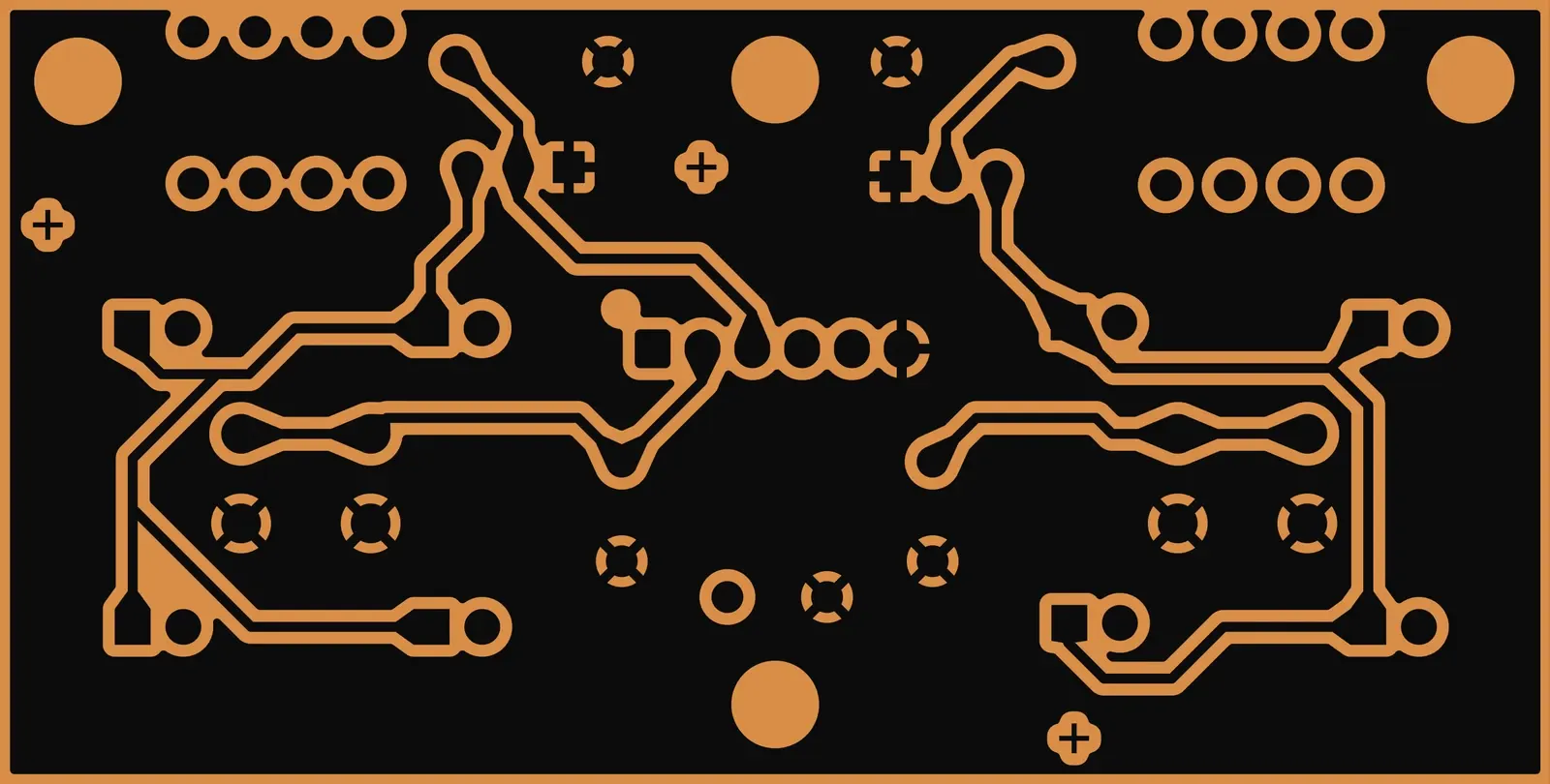
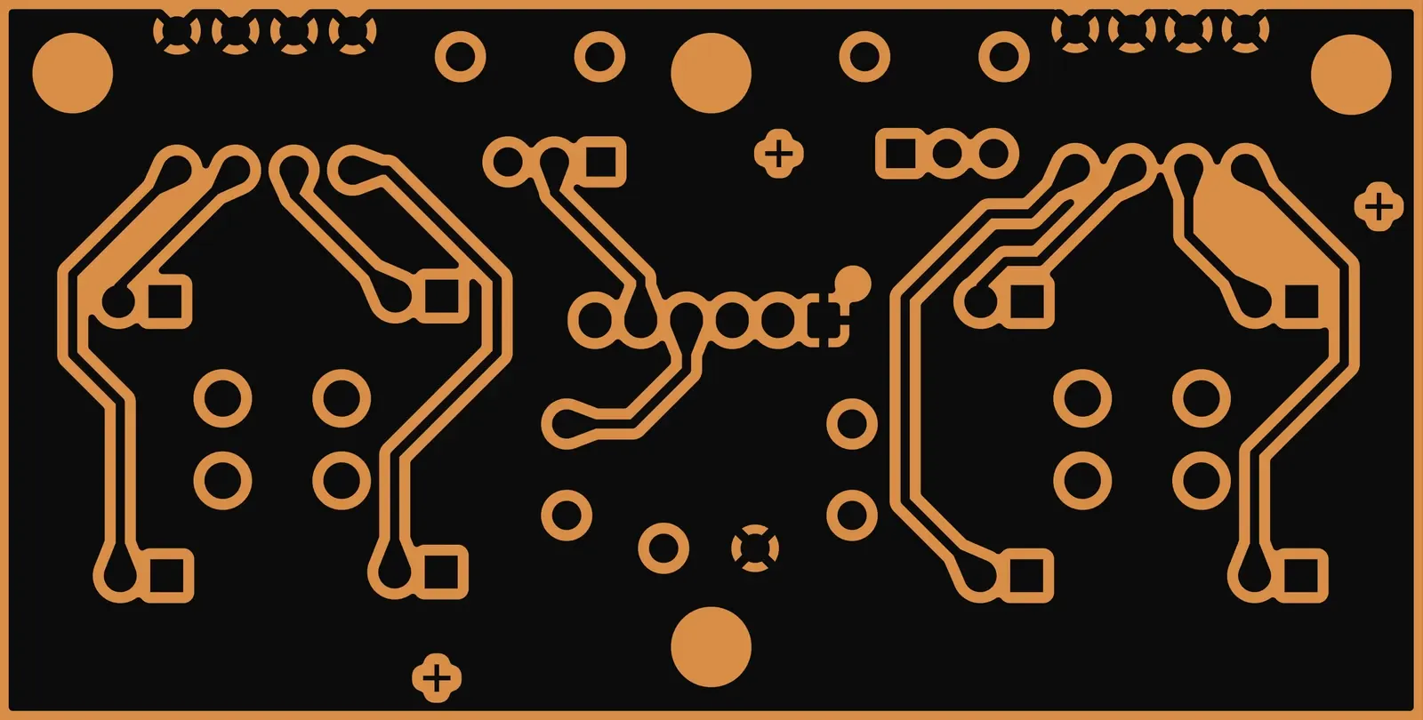
The play/cue and loop boards were first made in the workshop: KiCad's negative copper plots turned into laser files by a small script, the laser ablating a mask, ferric chloride doing the rest, and the holes drilled by hand. Getting the two sides to line up cost four attempts, all from a viewBox offset the laser software didn't clip to. Then the same boards were prepared for JLCPCB.

make_bambu_ready.py

The play/cue board's front copper as a laser file: the outlines of every track and pad around two switch footprints.
play_cue_btn's front copper, as the laser file draws it.
The same board's back copper as a laser file.
The back copper, for the other side of the same board.

A board, in 3D

Drag to turn · scroll to zoom · right-drag to move · arrow keys and + − tooDrag to turn · pinch to zoom · two fingers to move