One board to rule them all
TriMixxx began as a single 250 mm board carrying a Compute Module 5, a DAC, USB-C power and a MIDI controller. It was fully routed, and never built.

A CDJ is a computer, a sound card, a power supply and a control surface in one box, on a main board that does all of it. So the first plan for TriMixxx, in February 2026, was the obvious one: draw that main board, with open parts.
A CDJ on the bench
Before any schematic there was a real deck to learn from. In mid-February a Pioneer CDJ-1000MK3 was opened up, and its jog wheel, the part a DJ’s hand knows best, came out whole.
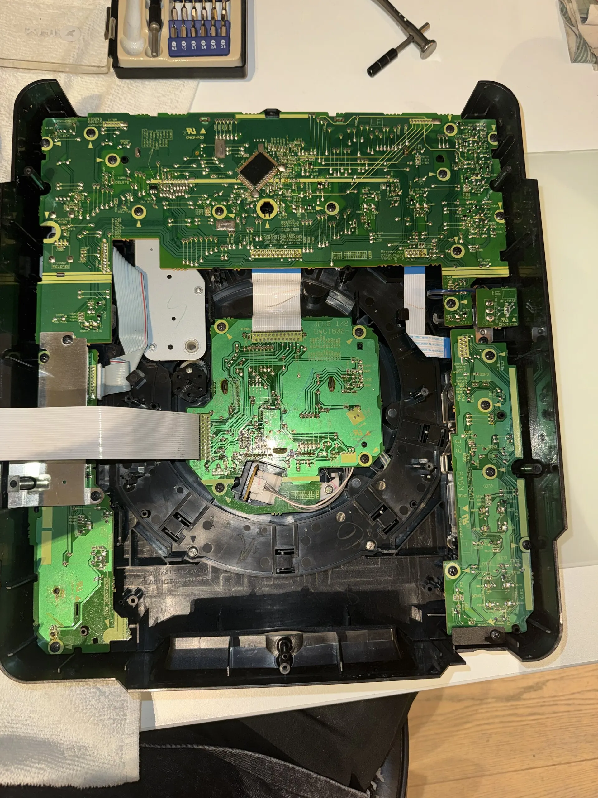
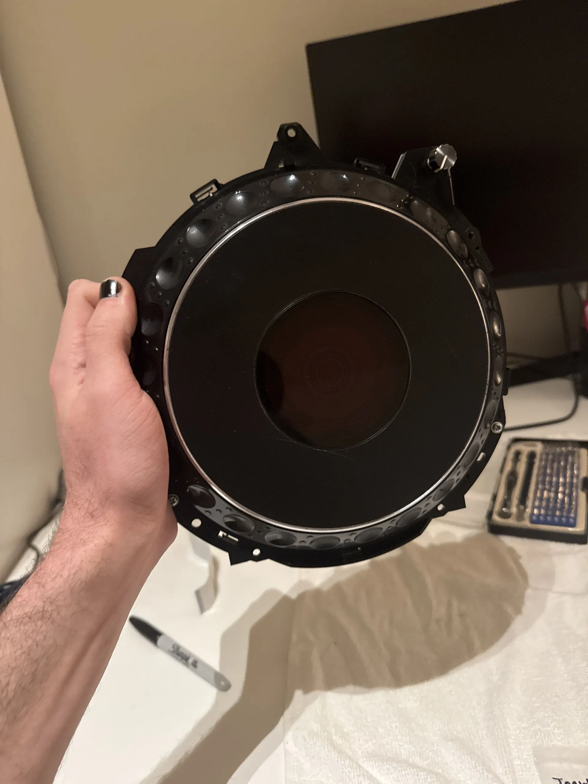
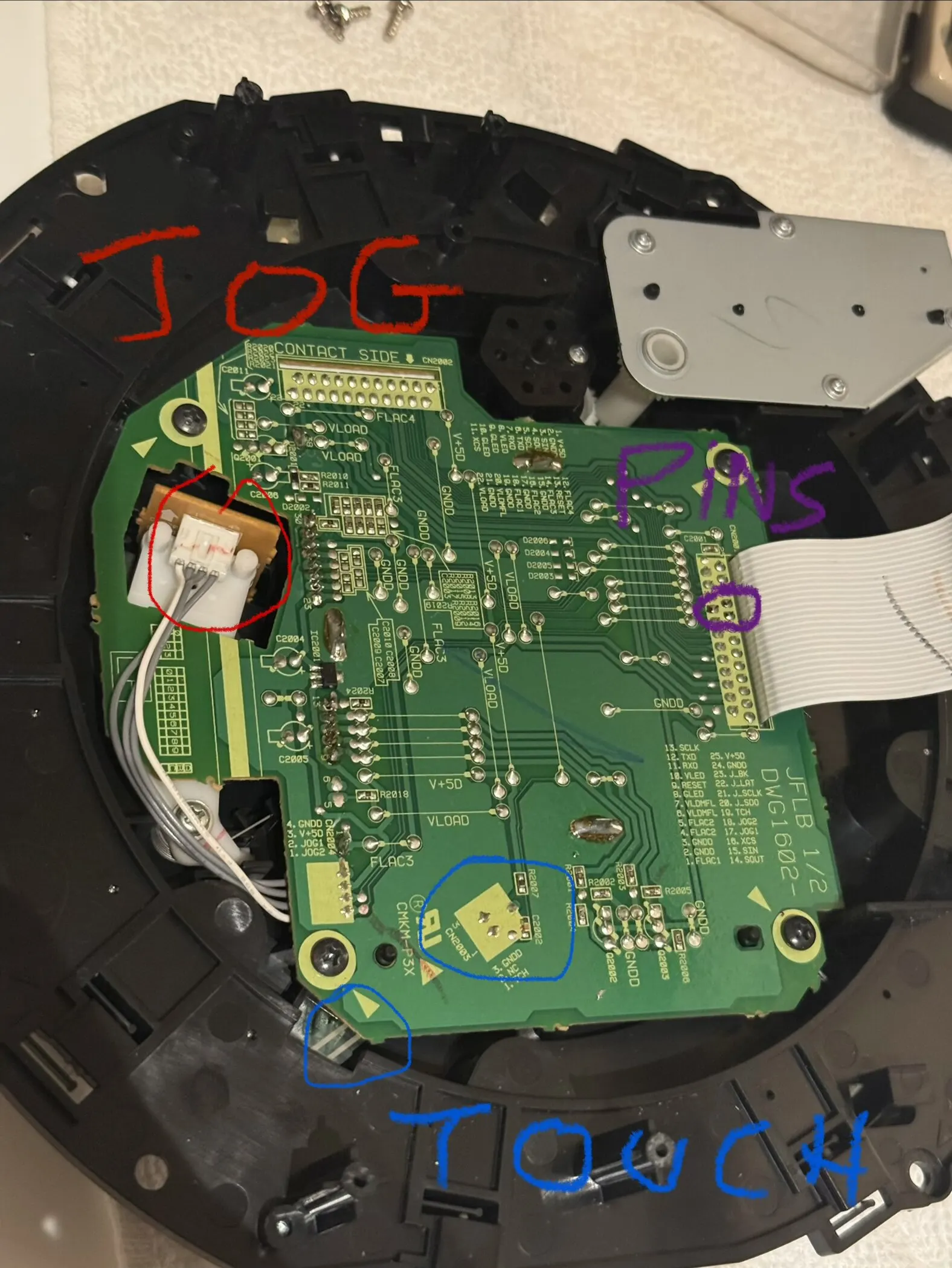
The jog’s own circuit board has three connectors: the optical encoder that counts the platter’s turns, a pin header, and the touch contact in the platter. By 23 February an Arduino was reading the encoder and counting pulses as the platter spun. Whatever else changed, the jog would stay a CDJ’s.
Everything on one PCB
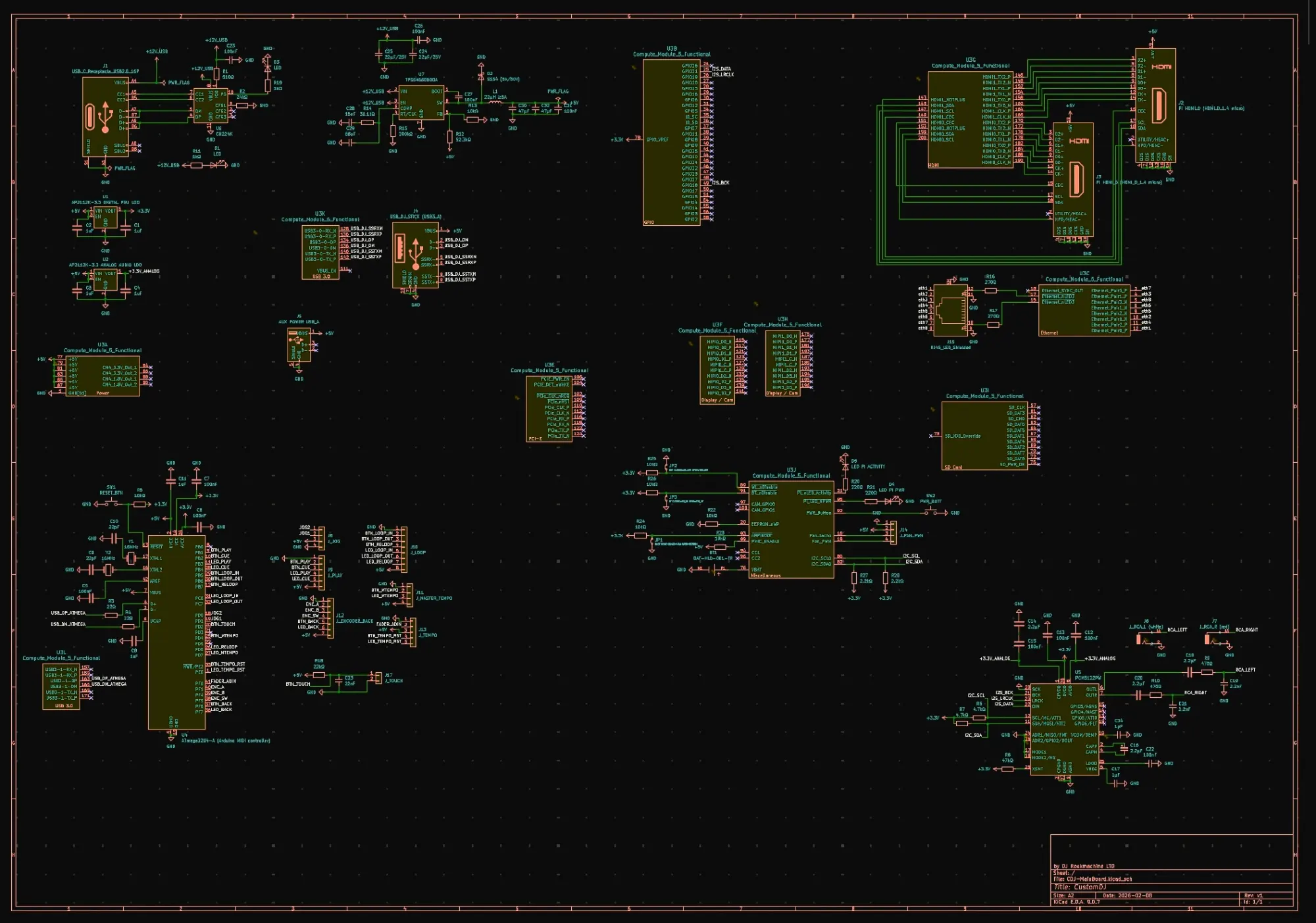
The board took shape in KiCad from 8 February. By March it carried:
- a Raspberry Pi Compute Module 5 on two 100-pin DF40 connectors, for the computer;
- a TI PCM5122 I²S DAC feeding RCA outputs and 6.35 mm and 3.5 mm headphone jacks;
- USB-C Power Delivery: a CH224K asking the charger for 20 V at 3 A, an SY8368AQQC buck down to 5 V, and AP2112K regulators for the logic;
- an ATmega32U4 presenting every button, the jog wheel and the tempo fader to the Compute Module as a USB-MIDI device, through MCP23017 expanders and a 74HC4067 analog multiplexer;
- two micro-HDMI ports, gigabit Ethernet, an SD card, and the USB ports the DJ’s sticks go into, behind HD3SS3220 and HD3SS3212 muxes and USBLC6 ESD protection.
About 160 components, on one board.
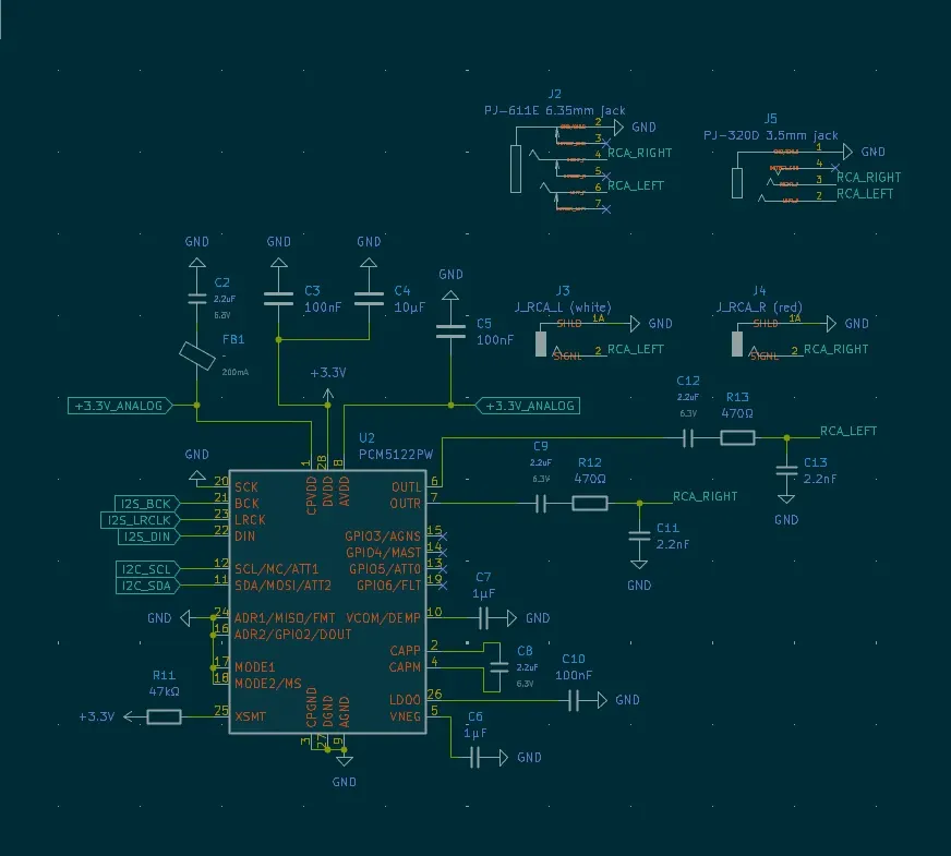
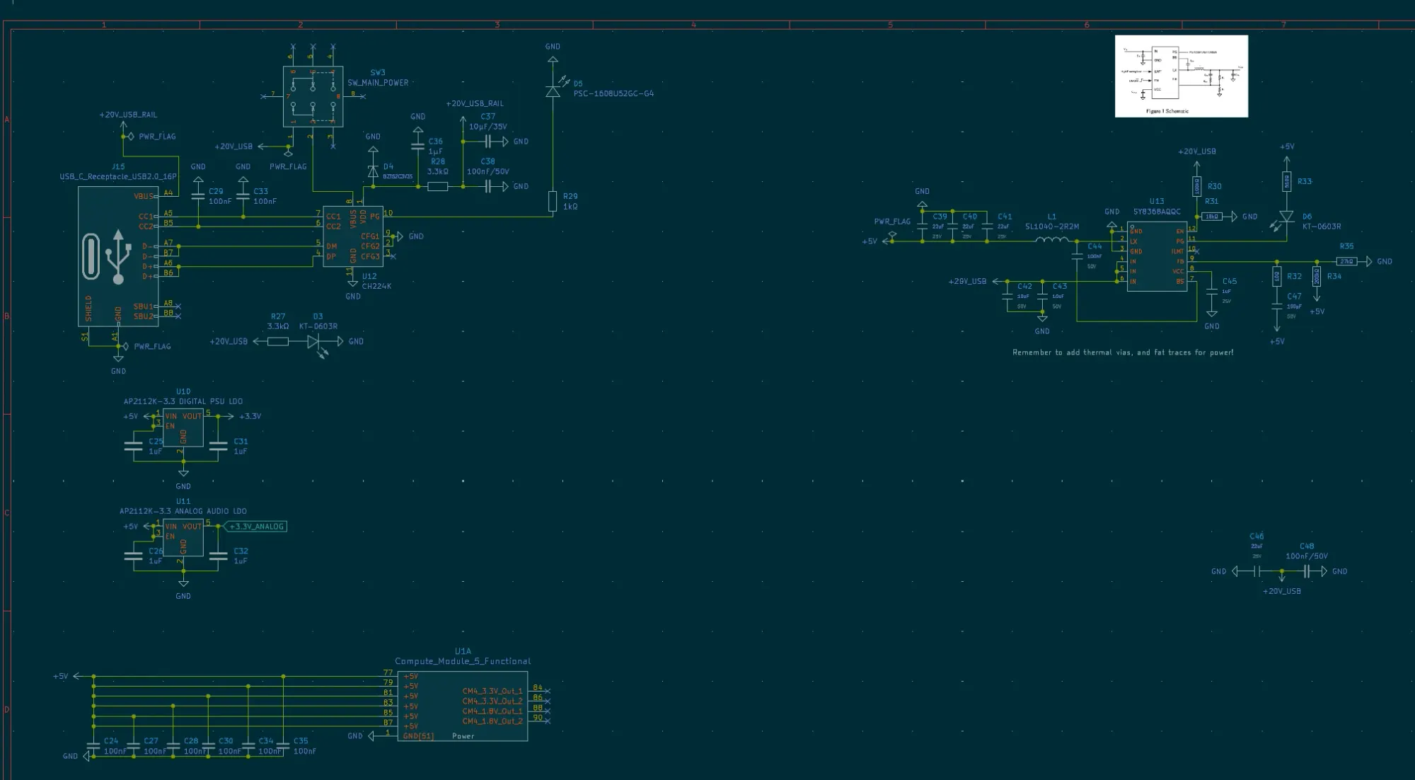
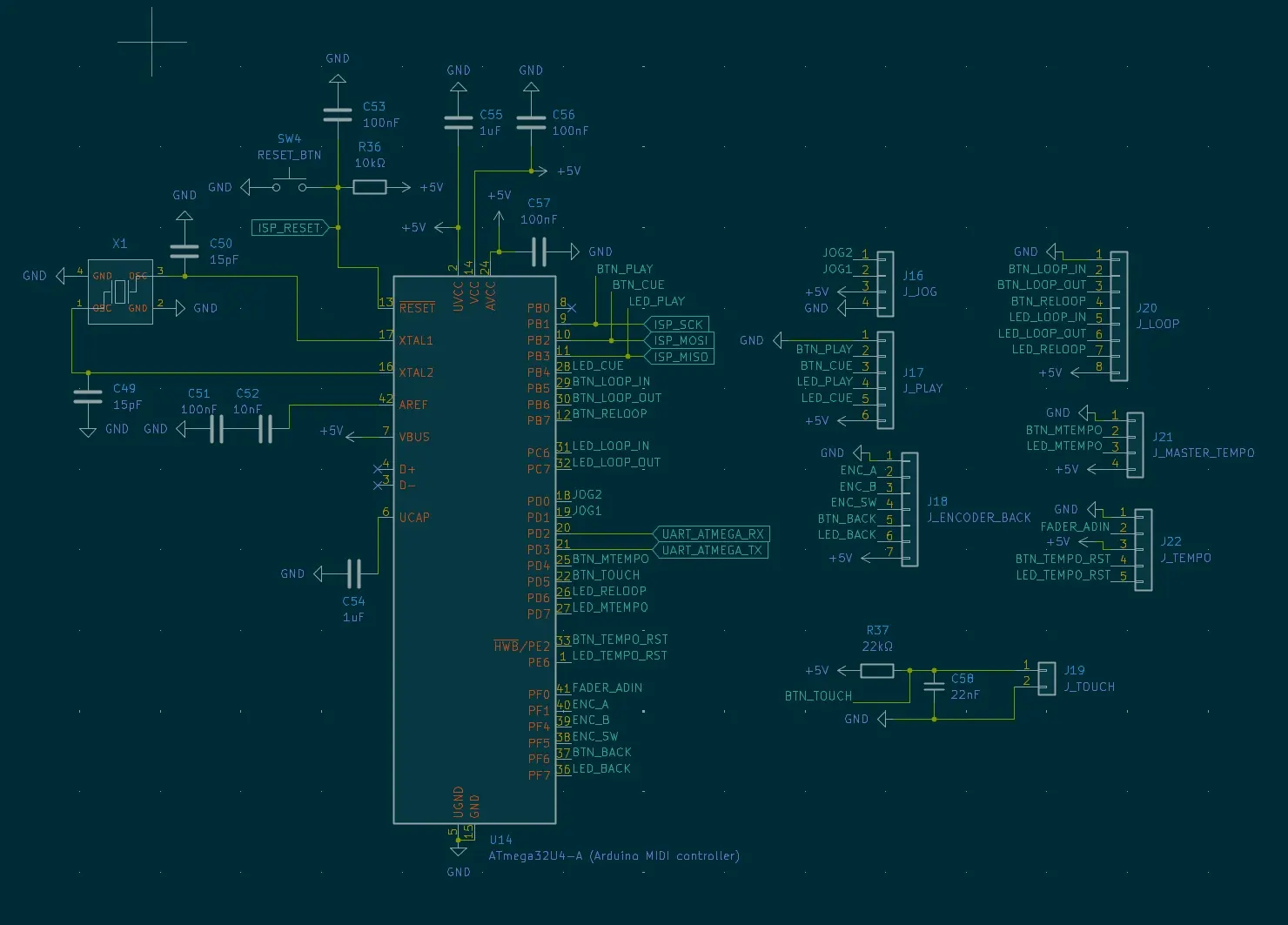
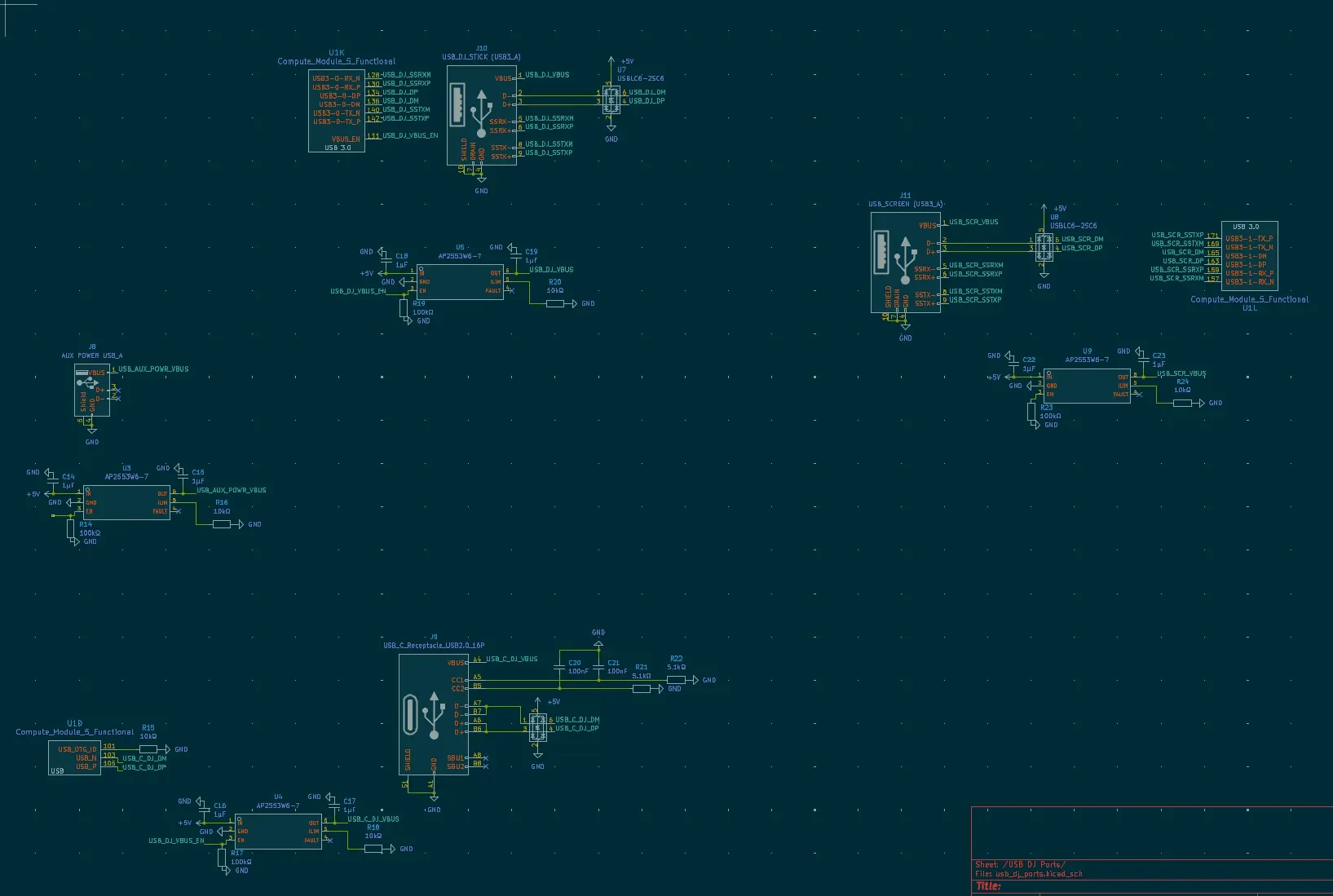
Simulate before you solder
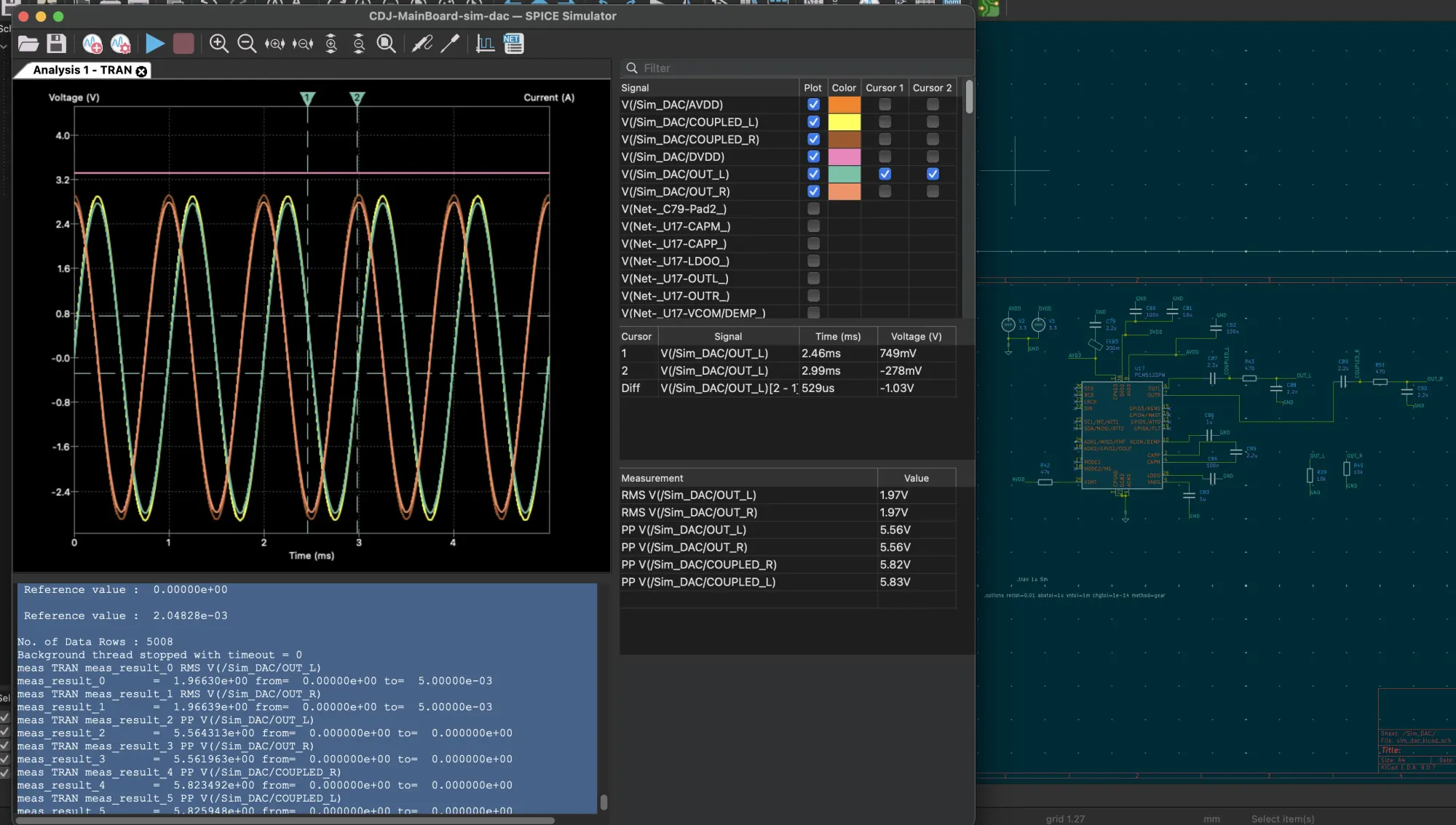
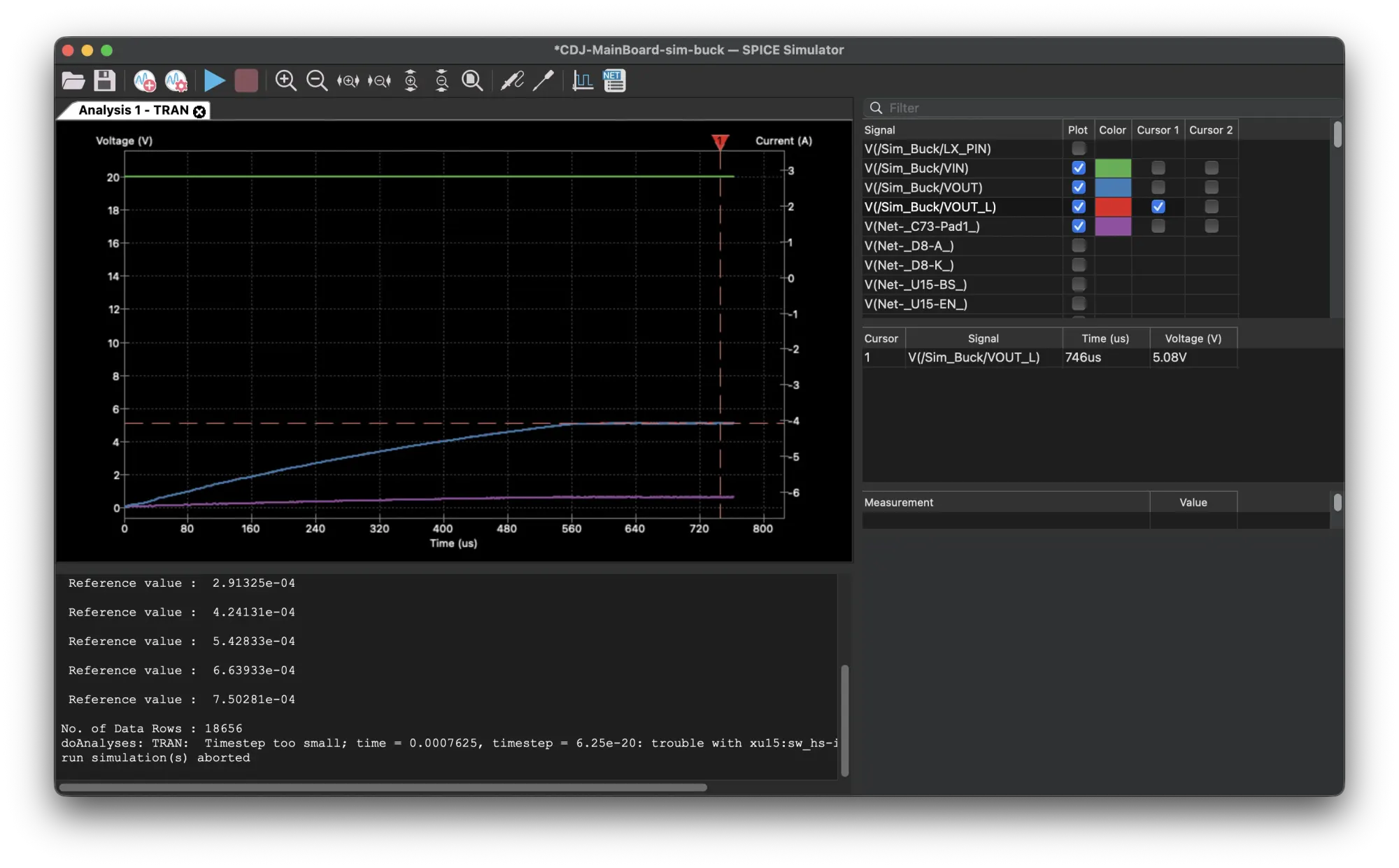
Two parts of the board were analog enough to be worth simulating first. On 11 March both went through SPICE in KiCad: the DAC’s output stage, to see what reaches the RCA jacks, and the buck converter, to see how 20 V becomes a clean 5 V under load.
Routing it
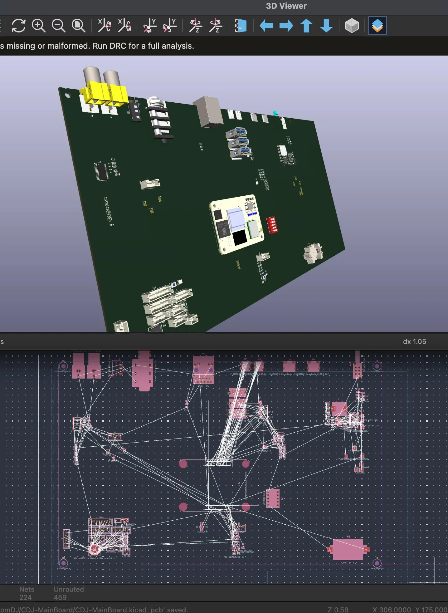
Then a week of routing, one subsystem a day: the buck, the two HDMI ports (with the via-in-pads taken out or tented), Ethernet, the four USB ports, the SD card, then audio and the microcontroller. On 26 March the board was finished: 250 × 104 mm, four copper layers, 210 footprints and 406 vias.
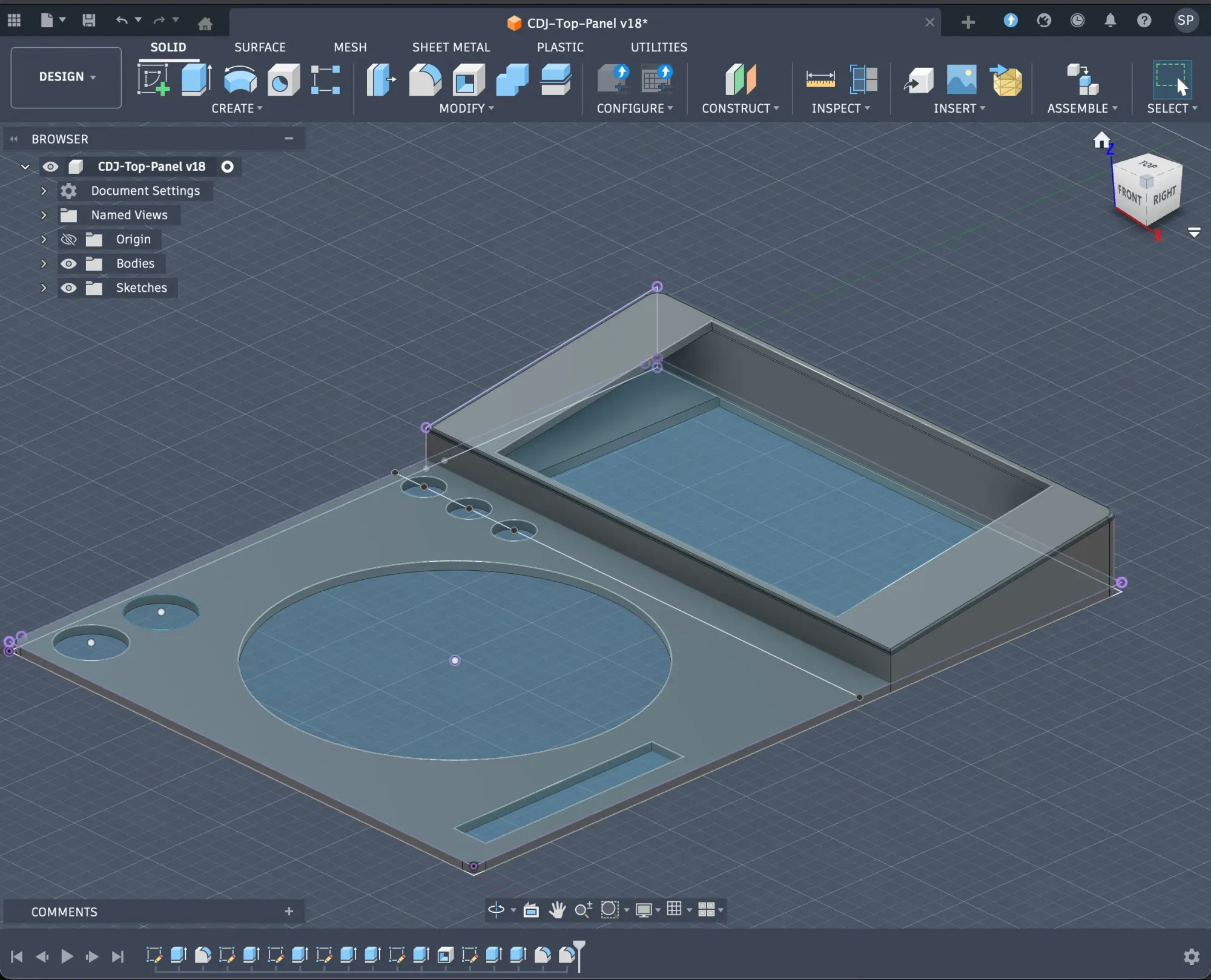
Meanwhile the top panel was taking shape in Fusion 360, with the cut-outs for the jog wheel and buttons:
Why it was never built
The board was finished, and never ordered. Looking back in July, the README put it plainly: cramming compute, audio, power and a controller onto one board made every revision expensive and every mistake fatal.
A wrong footprint on the USB-C controller would have meant a new board for the Compute Module too. A noisy ground under the DAC would have meant re-spinning the MIDI controller with it. And every one of those subsystems already existed, tested, on boards that cost less than a re-spin: a Raspberry Pi has its own power, HDMI and USB, and a USB sound card has its own DAC.
The idea that the deck’s controls should look like a MIDI device to the computer survived everything that came after. Only where that MIDI comes from changed.
So the next design started from the opposite end: use the boards that already exist, and only make the ones that don’t. The monolithic board’s sources were removed from the repository on 9 July. They survive in its history, with the schematics, the SPICE runs and the time-lapse, as the road not taken.